Expanded Metal Aluminum Panel Engineering for Ventilated Facades and Rainscreen Systems
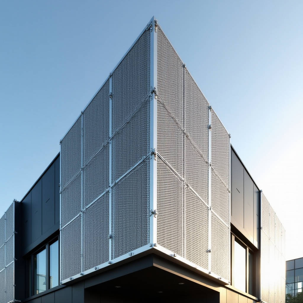
When a facade consultant specifies an Expanded Metal Aluminum Panel for a ventilated rainscreen, the conversation rarely stays on the panel itself for long. What follows is a cascade of questions about wind load deflection, perforation ratios, fastener pull-through values, and whether the specified alloy can hold a 12-mm return leg without cracking at the hem. These are not academic concerns. A miscalculated open-area ratio on a 30-meter tower in a coastal wind zone can turn a sunscreen into a liability. This article addresses the structural and fabrication realities that govern expanded metal aluminum panels in commercial cladding applications, with particular attention to alloy selection, flattening tolerances, and the testing protocols that separate a decorative screen from a code-compliant building envelope component.
What Actually Defines an Expanded Metal Aluminum Panel in Facade Engineering
The term gets thrown around loosely. An Expanded Metal Aluminum Panel is not a perforated sheet. It is not a welded wire mesh. It is a monolithic aluminum sheet that has been simultaneously slit and stretched under controlled tension, producing a network of diamond-shaped openings without any material loss. The process transforms a solid coil — typically 3003 or 5052 alloy — into a structurally integral mesh where each strand and bond node carries load continuously through the panel.
For facade applications, the distinction matters because the expansion process introduces work-hardening. A 3003-O sheet that enters the expanding press with a tensile strength of roughly 110 MPa can exit with localized yield strengths approaching 150 MPa in the strand zones. This is not a uniform property across the panel, and it creates anisotropic behavior that must be accounted for in wind load calculations. Engineers who treat expanded metal as isotropic are designing to failure.
The diamond pattern itself is classified by two critical dimensions: SWD (Short Way of Diamond) and LWD (Long Way of Diamond). In architectural specifications, SWD typically ranges from 6 mm to 34 mm, with strand widths between 1.5 mm and 6 mm. The open area percentage — the ratio of void to solid — can range from 20% to over 70%, and this number directly governs both the wind pressure coefficient and the visual transparency of the facade.
Raised vs. Flattened: The Tolerance Battle Nobody Discusses
Expanded metal aluminum panels come off the press in one of two conditions: standard (raised) or flattened. In the raised condition, the strands and bonds sit at an angle to the original sheet plane, creating a three-dimensional surface texture that catches light aggressively. The flattened condition passes the expanded sheet through a cold-rolling mill that presses all strands into a single plane, producing a smooth, two-dimensional surface.
The problem with flattening is tolerance accumulation. When a 4-foot by 10-foot panel goes through the flattening mill, the cold-working elongates the sheet by 3% to 7% in the LWD direction. If the fabricator does not compensate for this growth during the initial expansion setup, the finished panel will overshoot the specified dimensions. Worse, the flattening process can introduce camber — a curvature along the long edge that makes panel-to-panel alignment on a facade grid a nightmare for installers.
Specifiers should require a flatness tolerance of no more than 3 mm per linear meter for flattened panels intended for visible cladding zones. This is tighter than the ASTM F1267 standard default, but achievable with proper post-flattening leveling. Shops that skip the leveling step will deliver panels that read as wavy under grazing light conditions — a defect that becomes painfully obvious on south-facing elevations at 4 p.m.
Alloy Selection for Structural Cladding Applications
Not all aluminum alloys behave the same way inside an expanding press. The table below summarizes the key differences between the three alloys most commonly specified for expanded metal aluminum panels in facade work.
| Alloy & Temper | Tensile Strength (MPa) | Yield Strength (MPa) | Elongation (%) | Corrosion Resistance | Best Application |
|---|---|---|---|---|---|
| 3003-H14 | 150-200 | ≥125 | 8-12 | Good (atmospheric) | Interior screens, soffit liners, low-wind zones |
| 5052-H32 | 215-265 | ≥160 | 7-10 | Excellent (marine/coastal) | Exterior rainscreens, balcony balustrades, high-wind facades |
| 6061-T6 | ≥290 | ≥240 | 8-10 | Very Good | Security grilles, blast-rated screens (limited expandability) |
5052-H32 is the workhorse for exterior expanded metal aluminum panels. Its magnesium content (2.2%-2.8%) provides chloride resistance that 3003 cannot match in coastal environments. The trade-off is formability: 5052 work-hardens faster than 3003, which means tighter bend radii at panel edges require closer attention during brake forming. A 2.5-mm-thick 5052-H32 panel should not be bent to an inside radius smaller than 7.5 mm (3T) without risking stress-corrosion cracking at the hem.
6061-T6, while strong, is rarely expanded into architectural panels because its low elongation makes it prone to strand fracture during the expansion process. When it is used — typically for security applications — the expansion ratio must be reduced, resulting in a denser mesh with lower open area. This is a specialized product, not a general facade solution.
Wind Load Engineering for Open-Mesh Cladding
Solid aluminum cladding panels follow a well-established wind load calculation path: determine the design wind pressure per ASCE 7 or EN 1991-1-4, then check the panel's bending capacity against the tributary area per fastener. Expanded metal aluminum panels break this model because the wind passes through them.
The key parameter is the pressure coefficient Cp, which depends on the panel's solidity ratio (the inverse of open area). A panel with 40% open area has a solidity ratio of 0.60, and its effective Cp is not the solid-wall value of 1.0-1.4 but something closer to 0.30-0.50, depending on the diamond geometry and the angle of wind incidence. Wind tunnel testing by the American Architectural Manufacturers Association (AAMA) has shown that expanded mesh with SWD below 12 mm begins to behave aerodynamically like a solid surface at wind speeds above 40 m/s, because the boundary layer thickens across the small openings.
For preliminary design, engineers can estimate the reduced wind pressure as:
Pmesh = Psolid × (1 - 0.7 × φ) where φ is the open area ratio (0.0 to 1.0)
This is a rough approximation. For any project above 20 meters in height or in a wind zone exceeding 150 mph (67 m/s) basic wind speed, project-specific wind tunnel testing is the only defensible approach. The cost — typically $15,000 to $40,000 — is a fraction of what a failed facade costs to remediate.
Fastener Pull-Through: The Hidden Failure Mode
Expanded metal aluminum panels concentrate load at the bond nodes — the intersections where strands meet. When a fastener bears on a single strand near a panel edge, the pull-through capacity can be as low as 40% of what the same fastener would achieve in a solid sheet of identical thickness. This is because the strand offers a much narrower bearing area, and the expanded metal's work-hardened microstructure is more notch-sensitive than annealed sheet.
ASTM E488 provides the test method for determining pull-through resistance. For a typical 2.0-mm-thick 5052-H32 expanded panel with 3-mm strand width, tested with an M6 stainless steel fastener and a 16-mm-diameter washer, expected ultimate pull-through values range from 1.2 kN to 2.0 kN, depending on edge distance. Designers should apply a safety factor of 3.0 to these values, yielding an allowable load of 0.4-0.67 kN per fastener. This often dictates closer fastener spacing than the architectural team initially envisioned.
Futeng® has addressed this in past projects by supplying panels with reinforced edge bands — a solid 25-mm-wide perimeter strip left un-expanded during fabrication — which doubles the effective bearing area at edge fasteners without changing the visual openness of the panel field.
Coating and Finishing: PVDF on an Irregular Surface
Applying a PVDF coating to an expanded metal aluminum panel is not the same as coating a flat sheet. The three-dimensional strand geometry of raised expanded panels creates shadow zones during spray application. If the coating technician does not adjust the gun angle and line speed to account for the strand profile, the underside of each strand will receive less coating thickness than the top surface.
The AAMA 2605 standard for high-performance architectural coatings requires a minimum total dry film thickness of 30 microns (1.2 mils) on all visible surfaces. On expanded metal, "visible surfaces" includes the strand edges and the bond node sidewalls — areas that are geometrically challenging to coat uniformly. Specifiers should require the fabricator to submit cross-sectioned coating thickness measurements from at least three locations per production batch, including strand edge measurements.
For coastal installations, a three-coat PVDF system (primer + color coat + clear coat) is minimum. The clear coat should contain at least 70% PVDF resin by weight, per AAMA 2605 Table 1. Some manufacturers offer a four-coat system with a separate corrosion-inhibiting primer for projects within 500 meters of breaking surf. The additional cost — roughly $8-12 per square meter — is justified by the extended service life in chloride-rich atmospheres.
Anodizing Considerations
Anodized expanded metal aluminum panels present a different set of challenges. The expansion process creates micro-cracks in the aluminum oxide layer that forms naturally on the sheet surface. If the panel is anodized after expansion, these micro-cracks become initiation sites for uneven anodic film growth, resulting in visible streaking along the strand direction. The solution is to anodize the flat sheet before expansion — but this requires the anodized coating to survive the mechanical stress of the expanding press without spalling.
Only 5005 and 5052 alloys with controlled iron content (below 0.4%) are suitable for pre-anodize expansion. The anodic film thickness should be specified at Class I (18 microns minimum per The Aluminum Association DA-45) to provide sufficient ductility to survive the expansion process without visible cracking.
Fabrication Tolerances That Impact Installation
The expanded metal aluminum panel that leaves the fabricator's shop is rarely the final product. It goes to a secondary fabricator for cutting to size, edge forming, and attachment hardware integration. Each step introduces tolerance stack-up.
The table below summarizes the critical fabrication tolerances that should be specified in the project's aluminum cladding submittal package.
| Parameter | Recommended Tolerance | Measurement Method | Consequence of Non-Compliance |
|---|---|---|---|
| Panel diagonal (cut to size) | ±1.5 mm per meter | Steel tape, corner-to-corner | Panel racking in frame; uneven joint widths |
| Edge straightness | ±1.0 mm per linear meter | Straightedge + feeler gauge | Visible gaps at panel-to-panel joints |
| Flatness (flattened panels) | ≤3 mm per linear meter | Dial indicator on surface plate | Oil-canning; reflected light distortion |
| Strand width consistency | ±0.15 mm from nominal | Digital caliper, 10 points per panel | Inconsistent visual texture; variable strength |
| Hole diameter for fasteners | +0.5 mm / -0.0 mm | Go/no-go gauge | Fastener slop or binding during install |
These tolerances are tighter than what many general fabricators consider standard. A shop accustomed to producing industrial walkway grating will not instinctively work to facade-level tolerances. The specifier's job is to make the distinction clear in the bid documents and to require a first-article inspection before production quantities are released.
Fire Performance and Building Code Compliance
An expanded metal aluminum panel with more than 40% open area does not behave like a solid cladding element in a fire scenario. The openings allow hot gases to pass through, which can reduce the panel's contribution to flame spread but also means the panel does not function as a barrier to fire propagation between floors.
Chapter 14 of the International Building Code (IBC) classifies exterior wall coverings based on their performance in NFPA 285 testing. An expanded metal aluminum panel installed as part of a ventilated rainscreen system must be evaluated as part of the complete wall assembly, not as an isolated component. The panel's open area affects the ventilation rate within the cavity, which in turn affects the fire dynamics behind the cladding.
The National Fire Protection Association (NFPA) 285 test is the recognized standard for evaluating combustible components in exterior non-load-bearing wall assemblies. While aluminum itself is non-combustible (it melts at approximately 660°C rather than burning), the panel's geometry — specifically its open area and strand dimensions — influences how flames propagate through the assembly. Panels with SWD exceeding 20 mm and open area above 50% have been observed to allow more rapid flame penetration through the cladding layer in some assembly configurations.
Specifiers should request NFPA 285 test reports for the specific wall assembly configuration, not just for the panel product in isolation. An assembly that passed with a 4-mm-thick solid aluminum panel will not necessarily pass with an expanded panel of the same alloy, because the thermal and airflow characteristics are fundamentally different.
Supply Chain Realities: Lead Times and Mill Sourcing
Expanded metal aluminum panels occupy an awkward position in the supply chain. The aluminum coil is produced by a rolling mill, expanded by a specialist processor, and then often shipped to a third fabricator for cutting, forming, and finishing. Each handoff adds lead time and creates opportunities for miscommunication.
Typical lead times for architectural expanded metal aluminum panels break down as follows:
- Coil production (mill): 4-6 weeks for standard alloys, 8-10 weeks for 5052 with controlled chemistry
- Expansion processing: 2-3 weeks, depending on order volume and pattern complexity
- Flattening and leveling: 1-2 weeks (if not integrated with expansion)
- Fabrication (cutting, bending, hardware): 2-4 weeks
- PVDF coating: 2-3 weeks including pretreatment and curing
- Total: 11-18 weeks from order placement to shipment
This timeline assumes the project does not require custom tooling. If the specified diamond pattern is non-standard — an SWD of 9.5 mm with a strand width of 2.3 mm, for example — the expander may need to fabricate a custom die set, adding 4-6 weeks and $8,000-$15,000 to the project cost. The die cost is typically amortized across the project quantity, but for small orders under 500 square meters, it represents a significant per-unit premium.
For projects in North America, sourcing from domestic expanders eliminates the 6-8 weeks of ocean freight and customs clearance associated with overseas supply. However, domestic capacity for architectural-grade expanded aluminum is limited, and lead times can stretch during peak construction season (March-September). Early engagement with the supply chain — ideally during the design development phase — is the single most effective way to prevent schedule delays.
When Expanded Metal Aluminum Panels Are the Wrong Choice
An honest assessment includes knowing when not to specify a product. Expanded metal aluminum panels are not the right solution in several scenarios:
First, when the project requires a watertight building envelope. Expanded metal, by definition, is an open mesh. It can function as a rainscreen outer layer, but it cannot serve as the primary weather barrier. The waterproofing membrane behind the panel must be designed and detailed independently.
Second, when the architectural vision demands perfectly uniform openings. The expansion process produces diamonds with slight dimensional variation — typically ±0.3 mm on SWD — which is invisible at a distance of 3 meters but becomes noticeable upon close inspection. If the spec demands laser-cut precision, a perforated sheet is the correct product, not expanded metal.
Third, when the panel must span more than 1.2 meters between supports without intermediate framing. Expanded metal's effective section modulus is lower than that of a solid sheet of the same thickness, and deflection under wind load can exceed the L/60 limit commonly specified for cladding elements. Adding intermediate girts or stiffeners solves the problem but adds cost and visual clutter.
The ASTM International F1267 standard covers expanded metal specifications, but it is primarily written for industrial applications. Architects and engineers specifying expanded metal aluminum panels for facades should supplement F1267 with project-specific performance criteria covering flatness, coating adhesion (per AAMA 2605), and structural testing per ASTM E330 for wind load resistance.
Making the Specification Work: Practical Steps for the Project Team
A successful expanded metal aluminum panel installation starts with a specification that addresses the right parameters. Based on the technical issues discussed above, the following steps form a practical framework:
- Define the alloy and temper explicitly. Do not write "aluminum expanded metal." Write "5052-H32 aluminum expanded metal panel, flattened, with SWD of 12.7 mm and strand width of 2.5 mm, open area 55% ±3%." The alloy, temper, pattern dimensions, and open area tolerance are the minimum required information.
- Require a mock-up. A single panel viewed in isolation tells you nothing about how the facade will read across a 20-meter elevation. The mock-up should be at least 3 panels wide by 2 panels high, installed on the actual support system, and viewed under natural light at the same orientation as the final facade.
- Specify the coating inspection protocol. For PVDF-coated expanded panels, require dry film thickness measurements on strand tops, strand bottoms, and bond node sidewalls. Accept no less than 25 microns on any measured surface, with an average across all measurements of at least 30 microns.
- Address edge treatment in the fabrication drawings. Expanded metal panels have inherently rough edges where the mesh is cut. Specify whether edges will be left as-cut, deburred, or framed with a solid aluminum edge channel. The edge treatment affects both safety during installation and the visual quality of the finished facade.
- Plan for panel replacement. Expanded metal aluminum panels on a facade will, over a 30-year service life, sustain damage from impact, wind-borne debris, or maintenance activities. The specification should require the fabricator to supply 3-5% spare panels from the same production batch to ensure color and pattern consistency for future replacements.
The technical depth required to specify an expanded metal aluminum panel correctly is not trivial. But the alternative — a vague performance spec that leaves critical decisions to the lowest bidder — produces facades that look cheap, perform poorly, and generate disputes. For the architect and the engineer, the time invested in understanding the material's behavior pays back across every project that follows.