Expanded Aluminum Facade Engineering for High Rise Cladding Wind Load and Fatigue Design
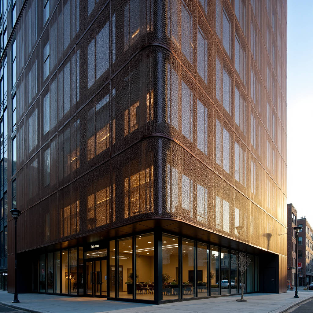
The specification process for an Expanded Aluminum Facade on high-rise structures demands a rigorous, numbers-driven approach that goes far beyond aesthetic preference. Architects and facade engineers who treat expanded aluminum mesh as a simple decorative screen often encounter costly failures: excessive deflection under wind load, galvanic corrosion at connection points, and acoustic resonance that turns a design feature into a liability. The core challenge lies in reconciling the open-area ratio required for visual transparency with the structural demands imposed by building height, local wind zones, and the mechanical properties of the specific aluminum alloy selected. An Expanded Aluminum Facade panel that performs beautifully on a three-story parking garage can become a dangerous projectile on a 40-story tower if the gauge, strand width, and fixing methodology are not recalculated for the elevated loads. This article examines the engineering variables that determine whether an expanded aluminum cladding system will meet code requirements across a 30-year service life, with particular attention to wind load calculation methodologies, alloy selection criteria, and the often-overlooked issue of fatigue performance in perforated metal envelopes.
Understanding the Mechanical Identity of Expanded Aluminum
Expanded aluminum mesh is produced by slitting and stretching a solid aluminum sheet in a single continuous operation. Unlike perforated metal, which removes material through punching and generates scrap, the expanding process reconfigures the base metal without waste. The resulting mesh consists of interconnected strands arranged in a diamond or hexagonal pattern, with each strand acting as a miniature structural member. The key geometric parameters are strand width (SW), strand thickness (ST), long way of opening (LWO), and short way of opening (SWO). These variables collectively determine the open area percentage, which typically ranges from 30% to 70% for architectural Expanded Aluminum Facade applications.
The mechanical behavior of expanded aluminum differs fundamentally from the parent sheet. The cold-working introduced during expansion increases yield strength in the strand direction by approximately 15-25% compared to the annealed condition of the same alloy. However, this strength gain is anisotropic—properties measured parallel to the LWO direction differ from those measured perpendicular to it. Testing data from multiple mill certifications shows that tensile strength in the transverse direction can be 10-18% lower than in the longitudinal direction. This anisotropy must be accounted for when orienting panels on a building elevation, particularly on facades where wind pressure vectors align with the weaker axis of the mesh.
Wind Load Calculations: The Governing Design Case
For any Expanded Aluminum Facade installed above 10 meters, wind load governs the design. The calculation methodology follows ASCE 7-22 in North America, EN 1991-1-4 in Europe, and AS/NZS 1170.2 in Australia and New Zealand. The fundamental equation appears straightforward: design wind pressure equals the velocity pressure multiplied by external pressure coefficients and a gust effect factor. However, applying this to expanded aluminum mesh introduces complications that do not arise with solid aluminum cladding panels.
The primary complexity is the aerodynamic porosity of the mesh. An Expanded Aluminum Facade with 50% open area does not experience the same pressure coefficients as a solid wall. Wind tunnel testing conducted at the University of Western Ontario's Boundary Layer Wind Tunnel Laboratory has demonstrated that pressure coefficients on porous cladding decrease non-linearly with increasing open area ratio. At 40% open area, the net pressure coefficient across the panel can be 30-40% lower than on a solid surface. At 60% open area, the reduction can reach 55-65%. However, these reductions apply only to the face of the panel. The supporting subframe behind the mesh may still experience near-full wind pressures if the mesh is mounted close to the backup wall, creating a confined air cavity.
Engineers must also consider the wind load on individual strands. Even when the overall panel pressure is reduced by porosity, localized pressures on each strand can be significant. The strand acts as a bluff body in cross-flow, generating drag forces that must be resisted by the strand's bending capacity. A strand with dimensions of 3mm thickness by 6mm width spanning a 50mm opening between nodes can experience bending stresses that exceed 60% of the material's yield strength under design wind speeds of 45 m/s. This is where many under-specified systems fail: the global panel calculation suggests adequate capacity, but the local strand-level analysis reveals a critical deficiency.
Alloy Selection: 3003, 5052, and the 5000-Series Advantage
The aluminum alloy chosen for an Expanded Aluminum Facade determines its corrosion resistance, strength, and formability. Three alloys dominate the architectural expanded metal market:
| Alloy | Yield Strength (MPa) | Tensile Strength (MPa) | Elongation (%) | Corrosion Resistance | Typical Thickness Range |
|---|---|---|---|---|---|
| 3003-H14 | 145 | 150-200 | 8-16 | Good (atmospheric) | 1.5 - 3.0 mm |
| 5052-H32 | 195 | 230-280 | 10-18 | Excellent (marine) | 1.5 - 3.0 mm |
| 5754-H22 | 185 | 220-270 | 12-18 | Excellent (marine/industrial) | 2.0 - 3.0 mm |
| 6061-T6 | 240 | 290-310 | 8-10 | Good (requires coating) | Not typically expanded |
5052-H32 has become the standard for architectural Expanded Aluminum Facade projects in coastal and industrial environments. The magnesium content (2.2-2.8%) provides resistance to chloride-induced pitting that far exceeds the 3000-series alloys. For projects within 5 kilometers of saltwater, 5052 or 5754 is essentially mandatory. The cost premium over 3003 is approximately 12-18%, but this is negligible compared to the remediation cost of premature corrosion on a high-rise facade.
6061-T6, despite its higher strength, is rarely used for expanded mesh because the T6 temper provides limited ductility. The expansion process requires the material to stretch considerably without fracturing at the strand intersections. 6061 in the T6 condition has elongation of only 8-10%, which is insufficient for patterns with tight LWO dimensions. Some manufacturers, including Futeng®, have developed processing routes that allow 5052 to be expanded in the H32 temper directly, avoiding the need for post-expansion heat treatment while maintaining consistent mechanical properties across the panel.
Fatigue Performance: The Overlooked Failure Mode
Wind-induced vibration subjects every Expanded Aluminum Facade to cyclic loading. While peak stresses during a single storm event may remain well below yield, the cumulative effect of millions of low-amplitude cycles over decades can initiate fatigue cracks at the strand nodes—the points where the mesh was stretched during manufacturing and where residual stresses are highest.
Fatigue testing of expanded 5052-H32 mesh, conducted per ASTM E466, reveals that the fatigue limit at 10 million cycles is approximately 85-95 MPa for strand-level bending stress. This is roughly 43-48% of the monotonic yield strength. If strand stresses under service wind conditions exceed this threshold, the design has a finite fatigue life rather than an infinite one. For a building with a 50-year design life in a region with moderate wind activity, the cumulative number of stress cycles can easily exceed 5 million, placing the design firmly in the high-cycle fatigue regime.
The practical implication is that allowable stress design for expanded aluminum mesh should incorporate a fatigue reduction factor of 0.40-0.50 on the yield strength, rather than the 0.60-0.72 factors commonly used for static design of solid aluminum elements. This is not currently codified in most building standards, which treat expanded metal as a generic cladding material without specific fatigue provisions. Engineers who rely solely on static allowable stress tables from manufacturers may be approving designs with inadequate fatigue margins.
Coating Systems and the PVDF Imperative
The coating specification for an Expanded Aluminum Facade presents unique challenges compared to flat sheet cladding. The three-dimensional geometry of expanded mesh means that coating thickness varies across the strand profile. Electrostatic spray application, the standard method for PVDF coatings, tends to deposit more material on the outer edges of strands and less in the recessed node areas. This phenomenon, known as the Faraday cage effect in powder coating or edge build-up in liquid coating, can result in coating thickness at the nodes being 40-60% of the nominal thickness on the strand faces.
For architectural applications, a 70% PVDF resin system applied to AAMA 2605 specifications remains the benchmark. The standard requires a minimum total dry film thickness of 30-35 microns for a two-coat system and 40-45 microns for a three-coat system. However, on expanded mesh, the specification should be written to require minimum thickness measurements at the strand nodes, not just on flat strand surfaces. This is more demanding and may require the applicator to adjust spray parameters, but it is essential for long-term corrosion protection.
An alternative gaining traction is the use of anodized finishes on 5000-series expanded mesh. Anodizing grows an aluminum oxide layer from the base metal itself, providing uniform coverage across complex geometries. The coating thickness for architectural Class I anodizing (AA-M12C22A31) is 18 microns minimum. While anodized finishes offer excellent uniformity on expanded mesh, the color range is limited compared to PVDF, and the process is sensitive to alloy composition—5052 with its magnesium content can develop a yellowish cast if not carefully controlled.
Subframe Design and Differential Thermal Movement
The subframe that supports an Expanded Aluminum Facade must accommodate differential thermal movement between the aluminum mesh and the supporting structure, which is typically steel or concrete. Aluminum expands at approximately 23.5 × 10⁻⁶ per °C, while structural steel expands at 12 × 10⁻⁶ per °C and concrete at 10 × 10⁻⁶ per °C. For a panel length of 4 meters subjected to a temperature range of -20°C to +70°C (a realistic range for a dark-colored facade in a continental climate), the differential movement between aluminum and steel is:
ΔL = (23.5 - 12.0) × 10⁻⁶ × 4000 × 90 = 4.14 mm
This may appear small, but if the connection detail does not allow for this movement, the resulting thermal stress can exceed 80 MPa—enough to cause buckling in thin-gauge expanded mesh or to loosen fixings over repeated thermal cycles. The subframe design should incorporate slotted connections or flexible brackets that permit in-plane movement while restraining out-of-plane deflection. Stainless steel brackets with elongated holes, combined with nylon shouldered washers at the mesh attachment points, provide a reliable solution that has been validated on multiple high-rise projects.
Acoustic Considerations for Perforated Building Envelopes
An Expanded Aluminum Facade with an open area exceeding 40% allows sound transmission through the building envelope with minimal attenuation. This is intentional for applications like parking garages, where natural ventilation is desired and acoustic privacy is not a concern. However, for mixed-use or residential towers, the acoustic performance of the expanded mesh layer must be evaluated as part of the overall wall assembly.
The sound transmission class (STC) of an expanded aluminum panel alone is essentially zero—it is acoustically transparent at most frequencies. The acoustic performance of the assembly depends entirely on what is behind the mesh. If the backup wall is a curtain wall system with insulated glazing, the STC rating is determined by the glass and framing. The expanded mesh contributes nothing to sound isolation but may introduce a secondary effect: cavity resonance. When the gap between the mesh and the backup wall is between 50mm and 300mm, the cavity can resonate at specific frequencies determined by the cavity depth. This can amplify external noise at those frequencies rather than attenuating it.
The solution is to either fill the cavity with acoustic insulation (mineral wool of 50-100 kg/m³ density) or to design the cavity depth to place the resonance frequency outside the range of concern—typically below 100 Hz or above 2000 Hz, where human hearing is less sensitive. Cavity depths greater than 400mm generally push the fundamental resonance below 100 Hz, which is a practical approach for deep facade systems.
Fire Performance and Code Compliance
Aluminum melts at approximately 660°C, which is well below the temperatures reached in a fully developed building fire (typically 800-1100°C). An Expanded Aluminum Facade will therefore lose structural integrity during a fire event. Building codes address this through requirements for non-combustibility, limited combustibility, or specific fire test performance, depending on the jurisdiction and building height.
Under the International Building Code (IBC), aluminum is classified as a non-combustible material per ASTM E136, but this classification applies only to the base metal. The coating system—particularly if it is a thick organic PVDF coating—may contribute to fire load. For buildings over 18 meters, many jurisdictions require the complete facade assembly to pass a large-scale fire test such as NFPA 285 (in North America) or BS 8414 (in the UK). The expanded mesh itself, being primarily aluminum, generally does not cause test failures. However, the combination of mesh, cavity, insulation, and backup wall must be tested as a system. Specifying an Expanded Aluminum Facade without verifying the fire test status of the complete assembly is a significant liability.
Cost Drivers and Value Engineering
The installed cost of an Expanded Aluminum Facade is driven by four primary factors: material gauge, pattern complexity, coating specification, and subframe design. The following table provides indicative cost ranges based on project data from 2022-2024:
| Cost Factor | Budget Range ($/m²) | Mid-Range ($/m²) | Premium ($/m²) | Key Variables |
|---|---|---|---|---|
| Expanded mesh (material only) | 45-65 | 70-95 | 110-150 | Alloy, thickness, pattern, open area % |
| PVDF coating | 25-35 | 40-55 | 60-85 | 2-coat vs 3-coat, color, gloss level |
| Subframe system | 35-50 | 55-80 | 90-140 | Steel vs aluminum, complexity, span |
| Installation labor | 40-60 | 65-90 | 100-150 | Height, access, panel size, fixing method |
| Total installed cost | 145-210 | 230-320 | 360-525 |
Value engineering efforts typically focus on optimizing the open area ratio. Increasing the open area from 40% to 55% reduces material weight by approximately 25%, which cascades into savings on the subframe (lighter loads allow wider bracket spacing) and installation (lighter panels require smaller lifting equipment). However, the structural implications must be carefully re-evaluated, as the remaining strands carry higher stresses. The most cost-effective Expanded Aluminum Facade designs are those where the open area ratio is maximized subject to the constraints of wind load capacity, visual screening requirements, and the desired aesthetic density.
Fabrication Tolerances and Site Coordination
Expanded aluminum mesh panels are fabricated to dimensional tolerances that are wider than those for solid aluminum cladding panels. The expansion process introduces inherent variability: the LWO and SWO dimensions can vary by ±1.5mm from the nominal specification, and panel flatness can deviate by up to 3mm per linear meter. These tolerances must be accommodated in the joint design between adjacent panels.
A common detail uses a 10-15mm open joint between expanded mesh panels, which absorbs fabrication tolerances while maintaining visual consistency. The joint also serves as a drainage path for water that penetrates the mesh, preventing moisture accumulation in the cavity. For projects where a tighter joint is architecturally desired, the panels can be fabricated with interlocking edges or a cover strip detail, but this increases cost and complicates installation sequencing.
Coordination between the expanded mesh supplier and the subframe contractor is critical. The mesh panel dimensions should be finalized only after the subframe bracket positions have been surveyed on-site. Even with precise shop drawings, concrete and steel tolerances of ±10mm at the bracket locations are common. Adjustable brackets with ±15mm of adjustment in three axes provide the necessary flexibility without requiring bespoke panels for each location.
Specification Checklist for Project Documentation
Writing a specification for an Expanded Aluminum Facade requires more detail than a typical cladding specification. The following items should be explicitly addressed in the project specification or schedule:
- Alloy and temper: Specify 5052-H32 as the minimum; require mill test certificates per EN 10204 Type 3.1 or equivalent.
- Mesh geometry: Define SW, ST, LWO, and SWO with tolerances. State the required open area percentage with an allowable range of ±5%.
- Coating: Reference AAMA 2605 for PVDF. Require minimum dry film thickness measurements at strand nodes, not just on flat surfaces.
- Wind load design: State the design wind speed, exposure category, and required factor of safety. Require calculations that address both global panel capacity and local strand bending.
- Fatigue: For high-rise or high-wind locations, require fatigue analysis demonstrating a design life of 50 years minimum.
- Fire: State the required fire test standard (NFPA 285, BS 8414, AS 5113) and require evidence of compliance for the complete assembly.
- Subframe: Specify material (aluminum or stainless steel), bracket spacing, and adjustment range. Require isolation between dissimilar metals.
- Mock-up: Require a visual mock-up of minimum 3m × 3m, erected on-site using the proposed subframe and fixing methodology, to be approved before production.
Suppliers such as Futeng® who maintain comprehensive technical documentation including wind load calculation reports, fatigue test data, and fire test certifications for their expanded aluminum systems can significantly streamline the specification review process. The engineering rigor applied at the specification stage directly determines whether the installed facade will perform as intended over its full service life.
The specification of an Expanded Aluminum Facade is fundamentally an exercise in applied mechanics, materials science, and building physics. Every decision—from the selection of 5052-H32 over 3003-H14 to the specification of node-level coating thickness measurements—has consequences that compound over the 30-50 year life of the building. The projects that succeed are those where the engineering team treats the expanded mesh not as a decorative screen but as a structural system that happens to be transparent. Wind tunnel data, fatigue curves, thermal expansion calculations, and fire test reports are not optional extras; they are the foundation of a defensible specification. When the engineering is done properly, the architectural result is a facade that combines visual lightness with genuine durability—a combination that solid cladding alone cannot achieve.