Corrugated Aluminium Facade Engineering How Rib Geometry and Alloy Selection Drive Wind Load Performance
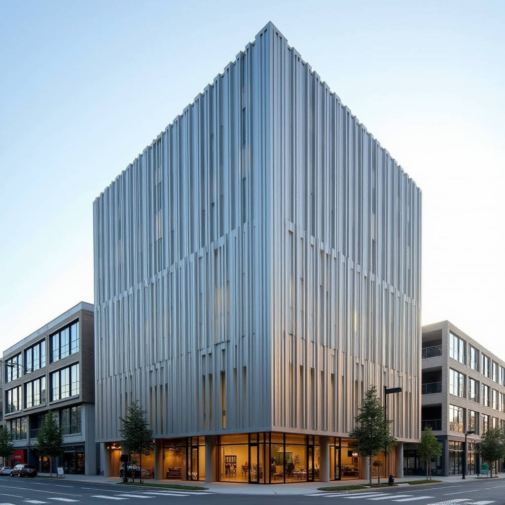
A Corrugated Aluminium Facade does more than wrap a building in texture. When specified correctly, the corrugation profile itself becomes a structural asset—stiffening the panel, controlling deflection under wind load, and dictating the rhythm of fastener placement. Yet too many specifications treat the profile as a visual afterthought, copying a generic trapezoidal rib from a catalogue without checking whether the geometry holds up under the project's actual wind zone. This article focuses on the engineering dimension that architects rarely see: how rib depth, pitch, alloy temper, and span interact to determine whether a solid aluminium corrugated panel performs or fails. Every calculation reference here applies to solid aluminium sheets—typically 2.0 mm, 2.5 mm, or 3.0 mm gauge in alloys 3003-H14 or 5005-H34—with PVDF coil coatings meeting AAMA 2605.
Why the Corrugation Profile Is a Structural Decision, Not a Style Choice
Flat aluminium panels spanning 1,200 mm between girts will deflect visibly under modest wind suction unless the gauge is pushed past 3.0 mm. That adds weight, cost, and handling complexity. Corrugating the sheet changes the arithmetic. A sinusoidal or trapezoidal rib with a depth of 30–40 mm can increase the section modulus by a factor of six to eight compared to a flat sheet of the same gauge. The result: a 2.0 mm corrugated aluminium panel can often outperform a 3.0 mm flat panel in deflection-limited design, while weighing roughly 30% less.
The mechanism is simple. Bending stiffness in a thin plate scales with the cube of thickness. A corrugation introduces geometric stiffness—the rib acts like a series of miniature beams running the length of the panel. The effective moment of inertia jumps, and the panel resists out-of-plane bending far more efficiently. But the gain is directional. Corrugated panels are stiff along the rib axis and relatively flexible across it. That anisotropy must be accounted for in the fixing layout. If the supporting substructure runs perpendicular to the ribs, the panel spans in its weak direction and the corrugation contributes almost nothing structurally.
For a Corrugated Aluminium Facade on a mid-rise commercial building in a wind zone with a design pressure of 1.8 kPa, a trapezoidal profile with 35 mm rib depth, 150 mm pitch, and 2.5 mm gauge in 3003-H14 alloy typically limits mid-span deflection to under L/180—comfortably within the serviceability criteria most façade consultants require. The same panel in 2.0 mm gauge might still pass ultimate strength checks but could exceed deflection limits, leading to visible waviness under peak gusts. That visual flutter erodes confidence in the entire envelope, even if no permanent deformation occurs.
Alloy Selection: 3003 vs. 5005 for Corrugated Profiles
Both alloys appear in corrugated aluminium façade specifications, but they serve different priorities. 3003-H14 offers higher formability, which matters when the corrugation profile has tight radii or deep draws. It bends more forgivingly through roll-forming stations without micro-cracking at the rib crests. 5005-H34 brings roughly 10–15% higher yield strength and better performance in marine or coastal environments due to its slightly different magnesium content. The trade-off: 5005 is marginally harder to form into deep profiles, and the springback after roll-forming can be more pronounced, requiring tighter process control at the mill.
For most commercial façades in inland environments, 3003-H14 with a PVDF coating provides an excellent balance of formability, corrosion resistance, and cost. For coastal projects within 5 km of breaking surf, 5005-H34 or even 5052-H32 becomes the safer call, paired with a thicker PVDF primer and a marine-grade pretreatment. The incremental material cost—typically 8–12% over 3003—is modest compared to the risk of filiform corrosion propagating from a cut edge or fastener hole.
Futeng® has supplied solid aluminium corrugated panels in both alloys across projects in Southeast Asia and the Middle East, and the engineering team routinely provides section property calculations for each profile before production, allowing the façade engineer to verify deflection against the specific wind load report rather than relying on generic span tables.
Wind Load Deflection: Calculating What Actually Matters
Most project specifications reference a deflection limit—commonly L/180 or L/240 for wall panels under wind load. The number looks straightforward, but applying it to a corrugated panel requires knowing the effective moment of inertia (Ieff) of the specific profile. That value is not intuitive. A trapezoidal rib 35 mm deep with a 150 mm pitch might yield an Ieff of 180,000–220,000 mm⁴ per meter width for a 2.5 mm gauge sheet, depending on the exact rib geometry. By comparison, a flat 2.5 mm sheet has an I of roughly 1,300 mm⁴ per meter width—two orders of magnitude lower.
The deflection under a uniform wind pressure p (in kPa) for a simply supported panel of span L (in mm) is:
δ = (5 × p × L⁴) / (384 × E × Ieff)
Where E for aluminium is approximately 70,000 MPa. For a 1,500 mm span under 2.0 kPa suction, a panel with Ieff = 200,000 mm⁴/m deflects roughly 8.5 mm—about L/176. That is borderline for an L/180 limit. Increasing the gauge to 3.0 mm pushes Ieff closer to 280,000 mm⁴/m and brings deflection down to around 6.0 mm (L/250). The choice between 2.5 mm and 3.0 mm gauge thus hinges on a few millimeters of calculated deflection, not on a gut feeling about "beefier" panels.
Wind tunnel testing or code-based pressure coefficients from ASCE 7, EN 1991-1-4, or AS/NZS 1170.2 should drive the design pressure. Corner zones on tall buildings can see pressures 2.5–3.0 times higher than the field zone, and panels in those zones may need a reduced span, a deeper profile, or a thicker gauge. A single panel profile across the entire façade is rarely optimal from a cost standpoint; zoning the panel specification by wind pressure region can trim 10–15% from the cladding material budget.
Thermal Movement: The Hidden Stress in Long Corrugated Runs
Aluminium expands at roughly 0.024 mm per meter per degree Celsius. A 6-meter-long corrugated panel subjected to a 60°C temperature swing (from a cold winter night to direct summer sun on a dark PVDF finish) will expand and contract by about 8.6 mm. If the panel is rigidly fixed at both ends, that movement translates into compressive or tensile stress that can buckle the panel or tear through fastener holes.
Corrugated profiles have a slight advantage over flat sheets here: the ribs can accommodate some axial movement through subtle flexing, acting like expansion bellows on a small scale. But this effect is limited and should not be relied upon as a substitute for proper slotting at fixings. The standard detail: fix the panel rigidly at one end (typically the top for vertical installations) and use slotted holes or sliding clips at all other fixing points. The slot length should accommodate the calculated thermal movement plus a safety margin of 2–3 mm.
For a Corrugated Aluminium Facade with vertically oriented ribs, thermal movement in the vertical direction is usually the dominant concern. Horizontal movement across the panel width is smaller because the panel width per piece is typically under 1,200 mm, limiting the absolute expansion. But if panels are joined with interlocking seams, the cumulative movement across multiple panels must be tracked, and expansion joints should be introduced every 8–10 meters of continuous run.
Fastener Placement and the Exposed vs. Concealed Fixing Debate
Corrugated panels can be fixed with exposed fasteners through the rib crests or with concealed clips that engage the rib geometry from behind. Exposed fasteners are cheaper and faster to install, but they puncture the weather barrier at every fixing point. Each fastener becomes a potential leak path, and the thermal expansion and contraction of the aluminium panel works the fastener hole over time, gradually enlarging it and degrading the seal.
Concealed clip systems avoid penetrating the panel face. The clip grips the rib profile mechanically, and the fastener that secures the clip to the substructure is shielded behind the panel. This approach preserves the integrity of the PVDF coating across the entire visible surface and eliminates the risk of water ingress at fasteners. The cost premium for concealed fixing is typically 15–25% in material and labor, driven by the more complex clip fabrication and the slower installation pace.
The table below compares the two approaches across key performance dimensions for a typical mid-rise commercial façade:
| Parameter | Exposed Fastener System | Concealed Clip System |
|---|---|---|
| Installed cost (USD/m², indicative) | 85–110 | 105–140 |
| Installation speed (m²/day/crew) | 40–60 | 25–40 |
| Water penetration risk at fixings | Moderate—relies on gasket/washer | Low—no face penetration |
| Thermal movement accommodation | Limited by fastener bearing | Clip design allows sliding |
| Panel replacement ease | Straightforward—unscrew and swap | More complex—requires sequential removal |
| Aesthetic | Visible screw heads on rib crests | Clean, uninterrupted rib lines |
| Typical maintenance cycle | Inspect gaskets every 5–7 years | Minimal—clips not exposed |
For projects in high-rainfall climates or coastal zones with salt spray, the concealed clip system's avoidance of face penetrations often justifies the cost premium over the building's service life. For interior applications or sheltered soffits, exposed fasteners may be entirely adequate.
Coating Durability: PVDF Performance on Corrugated Geometry
The corrugated profile introduces coating challenges that flat panels avoid. At the rib crests and valleys, the coil coating is stretched or compressed during roll-forming. A high-quality PVDF coating—typically a 70% PVDF resin system with a 25–35 micron dry film thickness—handles this deformation without cracking, but only if the coating was formulated and cured for post-forming. Not all PVDF coatings are equal. The key specification is whether the coating meets AAMA 2605, which requires passing a 10-year South Florida exposure test with a color change (ΔE) under 5.0 and gloss retention above 50%.
On a corrugated profile, the rib geometry also affects how rain and contaminants wash across the surface. Vertical ribs channel water downward efficiently, reducing the dwell time of acidic pollutants. Horizontal ribs can trap water in the troughs, leading to localized coating degradation if the drainage is insufficient. A minimum slope of 3–5 degrees is recommended for horizontally oriented corrugations to ensure positive drainage. The AAMA 2605 standard provides the full testing protocol for high-performance architectural coatings on aluminium.
Acoustic Considerations: Corrugated Panels and Rain Noise
Rain impact noise on metal façades is a frequent occupant complaint, particularly on buildings with lightweight backing walls or direct-fix systems without an acoustic break. Corrugated aluminium panels, being stiffer than flat sheets of the same gauge, can transmit impact noise differently. The rib geometry breaks up the panel's natural frequency and can reduce the drum-like resonance that flat panels exhibit. However, a solid aluminium panel without any damping layer will still generate noticeable sound when struck by heavy rain.
The most effective mitigation is to specify a factory-applied acoustic damping pad on the rear face of the panel. These pads—typically a bitumen-based or viscoelastic polymer layer 1–2 mm thick—convert impact energy into heat through internal friction. They can reduce rain noise by 6–10 dB, bringing the indoor sound level from potentially intrusive to background. The added cost is roughly USD 8–15 per square meter, and the pad must be compatible with the panel's fire rating requirements. For projects following ISO 10140 acoustic testing protocols, the damping pad can be the difference between a pass and a fail on internal noise criteria.
Fire Performance of Solid Aluminium Corrugated Panels
Solid aluminium panels are non-combustible—aluminium itself carries a Euroclass A1 rating as a raw material under EN 13501-1. However, a finished cladding panel is a system, not just the metal. The PVDF coating, any acoustic backing, and the substructure all contribute to the overall fire classification. A PVDF coating alone is typically thin enough (under 40 microns) to not affect the non-combustible classification, but thicker organic coatings or laminated acoustic pads may push the assembly into a different class.
For high-rise façades in jurisdictions that have tightened fire regulations—the UK post-Grenfell, the UAE Civil Defence code, and increasingly North American cities—specifying a solid aluminium corrugated panel with a pure PVDF finish and no combustible core is the baseline. The corrugation itself provides no fire performance benefit or penalty; the advantage lies entirely in the fact that there is no polyethylene or mineral-filled core to contribute fuel load. The ASTM E84 test (surface burning characteristics) and the full-scale NFPA 285 test for exterior wall assemblies are the relevant North American standards to reference in specifications.
Supply Chain Realities: Lead Times, Mill Sourcing, and Quality Control
Corrugated aluminium panels are not an off-the-shelf product for most architectural projects. The sequence typically runs: coil procurement from the rolling mill, coil coating at a certified PVDF applicator, slitting to width, roll-forming the corrugated profile, cutting to length, and fabrication of any edge returns, perforations, or clip-attachment features. Each step adds time and requires coordination.
Standard lead times from order to delivery run 6–10 weeks, depending on mill availability and coating line scheduling. Projects requiring custom profiles—where the rib geometry is not in the manufacturer's existing tooling set—add 2–4 weeks for roll-forming die fabrication. The most common bottleneck is the PVDF coating line, particularly for non-standard colors that require a dedicated run rather than a stock color that can be piggybacked onto an existing batch.
Quality control at the receiving end should include: checking the coating dry film thickness with a calibrated gauge (target: 25–35 microns, with no single reading below 80% of nominal), verifying the rib geometry against the approved shop drawing (depth, pitch, and radius tolerances typically ±1.0 mm), and conducting a visual inspection under diffuse daylight for coating defects. For projects exceeding 5,000 m², a third-party coating inspection to AAMA 2605 criteria is a prudent investment. The ASTM D7140 standard provides guidance on measuring coating thickness on aluminium substrates.
When Corrugated Aluminium Outperforms Other Façade Materials
Corrugated aluminium panels occupy a specific niche in the cladding spectrum. Compared to flat solid aluminium panels, they offer superior stiffness-to-weight ratio, allowing longer spans or thinner gauges. Compared to steel corrugated panels, aluminium eliminates the long-term corrosion risk without relying on galvanizing or paint integrity. Compared to fibre cement or terracotta rainscreens, aluminium corrugated panels are lighter (typically 7–9 kg/m² vs. 25–40 kg/m²), reducing the substructure and support loads.
The weight advantage compounds on retrofit projects where the existing structure has limited spare capacity. A Corrugated Aluminium Facade at 2.5 mm gauge weighs approximately 7.0 kg/m² including the coating. Add 2–3 kg/m² for the substructure and fixings, and the total cladding dead load is under 10 kg/m². That is low enough that many existing masonry or concrete-framed buildings can accommodate the new façade without structural upgrading—a decisive factor in adaptive reuse and over-cladding projects.
The natural reflectivity of aluminium also contributes to solar heat gain reduction. A bare or lightly tinted PVDF coating on aluminium can reflect 60–70% of incident solar radiation, reducing the cooling load on the backing wall. When combined with a ventilated cavity behind the cladding—the standard rainscreen configuration—the assembly provides both radiant and convective heat rejection. The cavity depth should be a minimum of 25 mm for drainage and 50 mm or more for meaningful thermal ventilation, per the Building Science Corporation rainscreen guidelines.
Making the Specification Work: Practical Engineering Checklist
Bringing a corrugated aluminium façade from concept to watertight envelope requires bridging the gap between architectural intent and engineering reality. The following checklist distills the key decision points that should be resolved before the panel order is placed:
- Profile geometry verified against wind load. Request the section properties (Ieff and Seff) from the panel manufacturer for the specific profile, gauge, and alloy. Do not accept generic "span tables" that do not reference the design wind pressure.
- Alloy and temper specified. 3003-H14 for standard applications; 5005-H34 or 5052-H32 for coastal or high-stress zones. Note the alloy on the shop drawings, not just in the spec book.
- Fixing system chosen: exposed or concealed. Match the system to the project's weather exposure, maintenance access, and budget. Concealed clips for high-rainfall/coastal; exposed fasteners acceptable for sheltered or interior locations.
- Thermal movement accounted for. Slot lengths calculated from the expected temperature range. Expansion joints detailed at 8–10 m intervals for continuous runs.
- Coating specification: AAMA 2605 PVDF. Minimum 25 microns dry film thickness. Color with a lightness value (L*) above 50 to reduce solar heat gain and minimize thermal movement.
- Drainage and ventilation confirmed. Minimum 3° slope for horizontal ribs. Ventilated cavity of 25 mm minimum behind the cladding.
- Fire strategy documented. Solid aluminium with PVDF coating for non-combustible baseline. Acoustic pads or insulation layers assessed for their contribution to the system fire rating.
- Quality control hold points defined. Coating thickness, profile geometry, and visual inspection at factory and on site.
A corrugated aluminium façade specified with these engineering fundamentals in place will perform reliably for decades. The profile is not just texture—it is the primary structural mechanism of the panel. Treat it as such from the first sketch, and the rest of the detailing falls into line.