Corrugated Aluminum Facade Engineering for Wind Load Performance and Subframe Economy
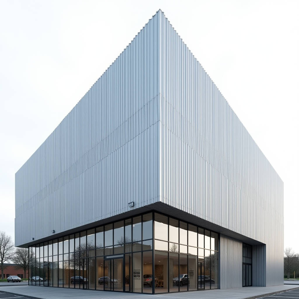
Wind load failure on a rainscreen facade is not something any contractor wants to explain to a client six months after handover. When the specification calls for large-format cladding with deep profiles, the structural conversation inevitably shifts to how the panel geometry itself resists deflection. A Corrugated Aluminum Facade solves this differently than flat sheet systems. The sinusoidal or trapezoidal rib profile introduces sectional stiffness that flat panels simply cannot match without increasing thickness—and that has direct consequences for spanning capability, fastener spacing, and ultimately installed cost. This article focuses on the engineering logic behind specifying corrugated solid aluminum panels where wind suction governs the design. We will walk through section modulus fundamentals, profile depth selection, alloy temper choices, and the connection between profile geometry and subframe economy. If you are a facade engineer, estimator, or procurement manager trying to reconcile architectural intent with wind tunnel data, the following sections should give you a practical framework.
Why Profile Geometry Matters More Than Plate Thickness
A flat 3.0mm aluminum panel spanning 1,200mm between girts will deflect under wind load in ways that a 1.5mm corrugated sheet with 25mm rib depth will not. The reason is section modulus. Bending stiffness in a flat plate scales linearly with thickness cubed (t³), which means doubling thickness from 1.5mm to 3.0mm increases stiffness roughly eight times. But introducing a corrugated profile—even at a lighter gauge—shifts the neutral axis further from the extreme fiber, multiplying the moment of inertia far more efficiently than adding mass. For a Corrugated Aluminum Facade, the profile depth and pitch are the primary levers for controlling deflection under wind suction, not raw material thickness.
This matters in high-wind zones. A project in coastal Queensland or the Gulf Coast might see design wind pressures exceeding 2.5 kPa. A flat 3.0mm solid aluminum panel on vertical girts at 600mm centers might pass, but push the girt spacing to 900mm and the same panel fails on deflection limits (typically L/175 or L/240 depending on the spec). A corrugated profile with 32mm depth and 150mm pitch can often span 1,200mm at similar or lighter gauge while staying within allowable deflection. The weight savings translate directly to fewer subframe members, fewer brackets, and less thermal bridging through the support system.
Fabricators should also note that corrugation introduces anisotropic behavior. Stiffness along the rib direction is dramatically higher than perpendicular to it. This directional stiffness must align with the primary span direction. Installing corrugated panels with ribs running horizontally when the span is vertical defeats the structural advantage. Site teams need clear shop drawings showing rib orientation relative to the support grid.
Alloy Selection: 3003 vs. 5052 for Corrugated Profiles
Not all solid aluminum sheet handles cold-forming into corrugated profiles equally. The two most common alloys in facade-grade corrugated sheet are 3003-H14 and 5052-H32. Both are non-heat-treatable wrought alloys, but their forming behavior and post-forming mechanical properties differ in ways that affect wind load performance.
3003-H14 offers excellent formability. It bends into tight corrugation radii without surface cracking, which is why many roll-forming operations prefer it. Yield strength sits around 145 MPa, tensile around 165 MPa. For moderate wind loads and standard profile depths (18-25mm), 3003-H14 is cost-effective and widely available in coil form. The trade-off: lower post-forming strength compared to 5052.
5052-H32 brings higher strength—yield around 193 MPa, tensile around 228 MPa—and significantly better corrosion resistance in marine and industrial atmospheres. The magnesium content (2.2-2.8%) provides that edge. However, 5052 is stiffer to form. Tight corrugation radii below 3T (three times material thickness) can risk micro-cracking at the rib crests if the roll-forming tooling is not optimized. For projects within 5km of breaking surf or in heavy industrial zones, 5052-H32 is the safer bet despite the forming challenges. The higher strength also means a 1.5mm 5052 panel can sometimes substitute for a 2.0mm 3003 panel in wind load calculations, saving weight without sacrificing capacity.
For reference, ASTM B209 governs aluminum sheet specifications for both alloys. Coil suppliers should provide mill test reports confirming temper and mechanical properties. A reputable processor like Futeng® maintains traceability from coil to finished panel, which becomes important when the specifier demands full material certification per project requirements.
Wind Load Calculation Framework for Corrugated Panels
Design wind pressure is determined per ASCE 7 in the United States, EN 1991-1-4 in Europe, or AS/NZS 1170.2 in Australia and New Zealand. The resulting design pressure (in Pa or kPa) is then applied to the panel as a uniformly distributed load. For a Corrugated Aluminum Facade, the panel is typically modeled as a simply supported beam spanning between girts or subframe rails, with the corrugation ribs acting as longitudinal stiffeners.
The key calculation steps are:
- Determine design wind pressure (positive and negative) per local code, including importance factors, exposure category, and internal pressure coefficients.
- Convert pressure to a line load based on panel width (tributary width per rib or per panel module).
- Calculate the section properties of the corrugated profile: moment of inertia (I) and section modulus (S) for the effective width. This can be done analytically for trapezoidal and sinusoidal profiles or extracted from manufacturer data.
- Check bending stress: σ = M/S, where M = wL²/8 for simple spans. Compare against allowable bending stress (typically 0.6 × yield for aluminum per the Aluminum Design Manual).
- Check deflection: δ = 5wL⁴/(384EI). Compare against allowable deflection limit (L/175 is common for wall panels, L/240 for more conservative specs).
- Check fastener pull-out and pull-over at the panel-to-subframe connection. Corrugated panels often use exposed fasteners at the rib crests or valleys, and the fastener capacity must exceed the tributary wind load per fastener.
Below is a practical comparison of three common corrugated profile configurations and their approximate spanning capabilities under a design wind pressure of 2.0 kPa (typical for mid-rise buildings in moderate wind zones):
| Profile Depth (mm) | Material Thickness (mm) | Alloy & Temper | Max Span at L/175 (mm) | Approx. Weight (kg/m²) | Typical Subframe Spacing (mm) |
|---|---|---|---|---|---|
| 18 | 1.5 | 3003-H14 | ~900 | 4.1 | 800-900 |
| 25 | 1.5 | 3003-H14 | ~1,200 | 4.1 | 1,100-1,200 |
| 32 | 1.5 | 5052-H32 | ~1,500 | 4.1 | 1,400-1,500 |
| 32 | 2.0 | 5052-H32 | ~1,650 | 5.5 | 1,500-1,650 |
| 38 | 2.0 | 5052-H32 | ~1,800 | 5.5 | 1,700-1,800 |
These spans assume simple supports and a continuous panel with ribs oriented parallel to the span direction. Actual values should be confirmed by a qualified structural engineer using manufacturer-specific section property data. The Aluminum Association's Aluminum Design Manual provides the complete methodology for allowable stress design of aluminum members.
Subframe Economy: How Corrugation Reduces Secondary Steel
The cost of a rainscreen facade is not just in the visible panel. Subframe—vertical girts, horizontal rails, brackets, and thermal isolators—often accounts for 30-45% of the total facade system cost. When a Corrugated Aluminum Facade can span further between supports, the subframe density drops. Fewer girts per floor height. Fewer brackets penetrating the insulation layer. Fewer thermal bridges to account for in the energy model.
Consider a 20-meter-tall building with girts at 1,200mm centers. Switching to a corrugated profile that allows 1,600mm centers eliminates roughly one girt per floor on a typical 4-meter floor-to-floor height. Across a 100-meter building perimeter, that is 25 fewer girt lines, each requiring brackets, fasteners, and labor for installation. The material saving on aluminum subframe or galvanized steel girts can offset the incremental cost of the corrugated profile tooling.
There is also a sequencing advantage. Wider subframe spacing means fewer obstructions for the insulation installer, fewer penetrations through the air and weather barrier, and less coordination between trades. The general contractor sees fewer days of crane time for subframe erection. These soft costs rarely appear in a unit-rate panel comparison but matter enormously at the project level.
Thermal performance improves as well. Each bracket penetrating the insulation layer is a point thermal bridge. Reducing bracket count by 25-30% directly lowers the linear thermal transmittance (Ψ-value) of the facade system, helping the building meet increasingly stringent energy codes such as ASHRAE 90.1 or the National Construction Code in Australia. The American Architectural Manufacturers Association (AAMA) publishes relevant thermal performance standards for rainscreen assemblies that specifiers should reference.
Coating Durability on Profiled Surfaces
Applying PVDF (polyvinylidene fluoride) coatings to a corrugated surface presents challenges that flat sheet coating does not. The rib crests and valleys experience different coating thicknesses during spray application. A conscientious coater adjusts spray parameters—gun distance, fluid flow rate, and electrostatic settings—to achieve uniform film build across the profile geometry. The specifier should require a minimum 25-micron dry film thickness measured at both the crest and valley of the corrugation, not just on a flat witness panel.
PVDF coatings based on 70% Kynar 500® or Hylar 5000® resin systems are the industry standard for exterior architectural aluminum. When properly applied to a Corrugated Aluminum Facade, these coatings provide 20-30 years of color retention and chalk resistance in most climates. The AAMA 2605 specification governs high-performance organic coatings on aluminum extrusions and panels. Compliance with AAMA 2605 means the coating has passed accelerated weathering tests including 4,000 hours of salt spray (ASTM B117), 10 years of South Florida exposure equivalence, and resistance to humidity, detergents, and acid pollutants.
For coastal or aggressive industrial environments, some specifiers opt for a three-coat system: a corrosion-inhibiting primer, a color coat, and a clear topcoat. The clear coat adds roughly 10-15 microns and provides additional UV screening. On 5052-H32 alloy, which already has inherent corrosion resistance, a two-coat system may suffice, but the decision should be based on the specific environmental exposure category per ISO 9223.
Below is a comparison of coating systems commonly specified for corrugated aluminum facade panels:
| Coating System | Resin Type | Typical DFT (microns) | Standard | Expected Service Life (years) | Best Suited Environment |
|---|---|---|---|---|---|
| 2-Coat PVDF | 70% Kynar 500® | 25-30 | AAMA 2605 | 20-25 | Urban, suburban |
| 3-Coat PVDF | 70% Kynar 500® | 35-45 | AAMA 2605 | 25-30 | Coastal, industrial |
| 4-Coat PVDF (metallic) | 70% Kynar 500® | 40-50 | AAMA 2605 | 25-30 | Premium architectural |
| FEVE (Fluoroethylene Vinyl Ether) | Lumiflon® | 30-40 | AAMA 2605 | 30+ | Extreme UV, coastal |
| Polyester (SP/PE) | Polyester | 20-25 | AAMA 2604 | 10-15 | Interior, sheltered |
FEVE coatings, based on Lumiflon® resin technology, are gaining traction in markets like Southeast Asia and the Middle East where UV exposure is extreme. They offer gloss retention superior to PVDF in some formulations, though at a higher cost. The choice between PVDF and FEVE should be driven by project-specific weathering requirements and budget. The ASTM B117 salt spray standard and ISO 9227 provide the testing framework for corrosion resistance validation.
Acoustic Considerations: Rain Noise and Corrugated Profiles
A common concern with metal facades is rain impact noise. Architects specifying a Corrugated Aluminum Facade for hotels, residential towers, or office buildings near quiet zones need to address this early. The good news: solid aluminum, even at 1.5mm, has enough mass to dampen rain noise better than thin steel cladding. The corrugated profile also helps—the ribs break up the flat surface that would otherwise act as a drumhead.
Measured rain noise levels for solid aluminum corrugated panels typically fall in the range of 45-55 dB(A) under heavy rainfall (simulated at 40mm/hour), compared to 55-65 dB(A) for 0.7mm steel trapezoidal sheets. Adding a perforated acoustic liner behind the panel, or specifying a mineral wool insulation layer in the cavity, can reduce transmitted noise by an additional 5-10 dB(A). The cavity depth between panel and insulation also matters: a 50mm cavity provides better acoustic decoupling than a 25mm cavity.
For projects where rain noise is a critical specification, request acoustic test data from the panel manufacturer. Tests conducted per ISO 140-18 (now superseded by ISO 10140 series) provide standardized rain noise measurement methodology. The ISO 10140 series covers laboratory measurement of sound insulation in building elements and should be referenced in performance specifications.
Fire Performance of Solid Aluminum Facade Systems
Solid aluminum panels are non-combustible (Euroclass A1 per EN 13501-1 when uncoated, A2-s1,d0 with PVDF coating). This is a critical distinction from aluminum composite panels with polyethylene cores, which have been implicated in several high-profile facade fires globally. A Corrugated Aluminum Facade using solid 3003 or 5052 sheet with PVDF coating will typically achieve A2-s1,d0 classification, meaning no significant smoke production and no flaming droplets.
However, the complete rainscreen system—including insulation, weather barrier, and subframe—must be evaluated as an assembly. The panel itself may be non-combustible, but if the insulation behind it is combustible PIR foam without adequate fire stops, the system-level fire performance is compromised. Specifiers should require full-scale facade fire testing per NFPA 285 (USA), BS 8414 (UK), or AS 5113 (Australia) for the complete build-up, not just the panel material.
Solid aluminum's high melting point (approximately 660°C for pure aluminum, slightly lower for 3003 and 5052 alloys) means the panel retains structural integrity longer than materials with lower melting points. In a fire scenario, this can delay flame penetration through the facade and provide additional time for occupant evacuation. The panel fixings should be stainless steel (304 or 316 grade) to maintain connection integrity at elevated temperatures—aluminum fasteners will fail before the panel itself.
Installation Tolerances and Interface Detailing
Corrugated panels introduce specific interface challenges that flat panels avoid. At window heads and sills, at parapet caps, at base flashings—the corrugated profile must be terminated cleanly. The standard approach is to use a flat flashing piece that laps over or under the corrugated panel, with the profile cut to match the corrugation contour. This requires accurate shop drawings and precise fabrication.
Panel-to-panel joints in a Corrugated Aluminum Facade typically use a side-lap detail where one panel's edge rib overlaps the adjacent panel. The overlap should be a minimum of one full rib (typically 30-50mm) and include a weather seal or gasket to prevent wind-driven rain ingress. For exposed fastener systems, fasteners are placed through the overlap at the rib crest, with EPDM sealing washers under the fastener heads. The fastener spacing along the joint should match the subframe spacing and be verified against wind load calculations.
Thermal movement must also be accommodated. Aluminum expands at approximately 23 × 10⁻⁶ per °C. A 6-meter-long panel subjected to a 60°C temperature swing (from -10°C in winter to 50°C surface temperature in summer sun) will expand roughly 8.3mm. Fixed points and sliding connections must be detailed to allow this movement without buckling the panel or overloading the fasteners. The Aluminum Association provides detailed guidance on thermal movement accommodation in aluminum building products.
Procurement and Lead Time Realities
Corrugated solid aluminum panels are not an off-the-shelf product. The corrugation profile is typically roll-formed from flat coil stock, then cut to length, and coated (if not using pre-painted coil). Tooling for a specific corrugation profile—especially if the architect has designed a custom rib pitch or depth—can add 4-8 weeks to lead time and a one-time tooling charge that must be amortized across the project.
Standard profiles (sinusoidal 18/76, 25/150, or trapezoidal 32/200) are available from multiple processors and can typically be delivered in 6-10 weeks from order confirmation, depending on coating complexity and project size. Custom profiles require tooling manufacture, trial runs, and sample approval before production begins—plan for 12-16 weeks minimum.
For international procurement, containerized shipping of corrugated panels requires careful packing. Nesting panels face-to-face with protective interleaving prevents coating damage during transit. The corrugated geometry means less efficient container utilization compared to flat sheets—expect 15-25% more volume per square meter of panel area. This should be factored into the landed cost estimate. Suppliers with established export packaging protocols, such as Futeng®, can advise on optimal container loading configurations to minimize freight cost per square meter.
When evaluating supplier quotations, ensure the scope includes: material certification (mill test reports to EN 10204 3.1 or equivalent), coating warranty (typically 20 years for PVDF from coating manufacturer), profile dimensional tolerances (width ±2mm, length ±3mm, rib depth ±1mm), and packaging suitable for the shipping method. Exclusions to watch for: subframe, fasteners, shop drawings, and site installation—these are often quoted separately and can significantly change the total installed cost picture.
Making the Engineering Case to the Project Team
Specifying a Corrugated Aluminum Facade on wind load grounds requires more than a calculation package. The facade engineer needs to communicate the value proposition to the architect (who cares about the visual rhythm of the corrugation), the cost consultant (who sees the subframe reduction), and the main contractor (who manages the installation sequence).
The most persuasive argument is usually the subframe savings. If a corrugated profile allows girt spacing to increase from 1,000mm to 1,400mm, the reduction in linear meters of subframe, brackets, and associated labor is quantifiable. On a project with 5,000m² of facade area, that difference can represent tens of thousands of dollars in secondary steel and installation hours. When the cost consultant sees that the higher panel unit rate is more than offset by subframe and labor savings, the specification holds.
For the architect, the corrugation depth and pitch are aesthetic parameters as much as structural ones. Shadow lines cast by the ribs change throughout the day. A deeper profile (32-38mm) creates stronger shadow definition, which can emphasize the building's horizontal or vertical lines depending on orientation. The specifier should provide physical samples showing the profile under different lighting conditions—a flat sample viewed in an office does not represent how the facade reads from 20 meters away in sunlight.
Wind load performance is ultimately a safety and serviceability issue. A panel that deflects excessively under wind suction is not just a cosmetic problem—it can fatigue the coating at fastener points, loosen connections over time, and in extreme cases, detach from the building. The engineering rigor applied to profile selection, span tables, and fastener design is what separates a facade that performs quietly for 30 years from one that generates callbacks. Solid aluminum corrugated panels, correctly specified and installed, deliver that performance without the complexity or risk profile of more exotic facade materials.