Perforated Aluminium Facade Engineering Limits Open Area Panel Size and Structural Reality
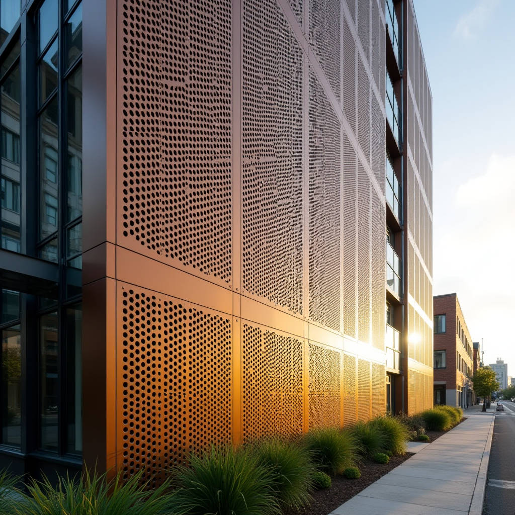
The specification of a Perforated Aluminium Facade on a commercial project triggers a cascade of engineering decisions that go far beyond selecting a hole pattern. Architects push for openness ratios above 35% to achieve visual lightness, while structural engineers wrestle with wind load paths across a panel that has been systematically weakened by thousands of punched openings. The tension between these two demands is where most tender-stage mistakes happen. A panel that looks stunning in a render can become a warranty nightmare if the perforation layout ignores stress concentrations at panel corners, the reduced section modulus at fixing points, or the galvanic environment created by the supporting steelwork. This article works through the structural and fabrication limits that define what can actually be built, from hole geometry constraints to the practical ceiling on open area percentages for solid 2.5mm and 3.0mm aluminium sheets.
Solid Aluminium vs. Composite: Why the Base Material Dictates Perforation Limits
Solid aluminium sheet, typically specified at 2.0mm, 2.5mm, or 3.0mm thickness under EN 485 or ASTM B209, behaves fundamentally differently from aluminium composite material when perforated. A solid 3.0mm 3003-H14 or 5052-H32 sheet retains a continuous metallic grain structure across the entire panel. When you punch 10,000 holes in it, the remaining material is still a single piece of wrought aluminium with predictable isotropic mechanical properties. The same cannot be said for ACP, where perforation severs the bond between the 0.5mm skins and the polyethylene core, creating a moisture ingress path and a structural discontinuity at every hole edge.
This matters because the yield strength of a solid 3.0mm 5052-H32 sheet sits around 193 MPa, and the panel's bending stiffness is a function of its intact thickness cubed. Every hole removes material from the cross-section, but the remaining web of aluminium between holes still carries load through a continuous crystalline structure. The effective section modulus of a perforated panel can be estimated using the equivalent solid material concept: a panel with 30% open area behaves structurally like a solid panel of roughly 70% of the original thickness for bending calculations. For a 3.0mm sheet at 30% openness, the effective bending thickness is approximately 2.1mm. This is a rule-of-thumb starting point; finite element analysis is mandatory for any facade with open areas exceeding 20% or panel dimensions beyond 1,200mm in any direction.
Hole Geometry, Edge Distance, and the Stress Concentration Factor
The shape of a perforation is not a purely aesthetic choice. Round holes produce the lowest stress concentration factor (Kt) of any hole geometry, typically around 2.5 to 3.0 for a single hole in an infinite plate under uniaxial tension. Square holes with sharp corners push Kt above 4.0, and triangular or irregular cutouts can drive it higher still. In a Perforated Aluminium Facade, these stress concentrations multiply when holes are arranged in close proximity, because the stress fields of adjacent holes interact.
The critical parameter is the ligament efficiency: the ratio of the minimum distance between adjacent hole edges (the ligament) to the hole diameter. For a 10mm diameter round hole on a staggered 60-degree pitch, if the centre-to-centre spacing is 15mm, the ligament is 5mm. The ligament efficiency is 5/10 = 0.5, or 50%. Industry practice for structural facade panels sets a minimum ligament efficiency of 50% for non-structural zones and 75% for areas around fixing points. Below these thresholds, the panel transitions from a perforated sheet to a mesh, and the structural analysis assumptions change completely.
Edge distance is equally important. The distance from the centre of any hole to the nearest panel edge should be at least 1.5 times the hole diameter, and preferably 2.0 times. A 10mm hole should sit no closer than 15mm from the panel edge, and 20mm is safer. Violating this rule creates a tear-out risk during handling and wind loading, where the small sliver of aluminium between the hole and the edge fails in shear.
Open Area Percentage: The Practical Ceiling for Solid Aluminium Panels
Open area percentage is the single number most architects fixate on, and it is the number most frequently misapplied in specification. It is calculated as the total area of all perforations divided by the total panel area, expressed as a percentage. A panel with 10mm round holes on a 15mm staggered pitch achieves approximately 40% open area. The same panel with 10mm holes on a 20mm pitch drops to around 23%.
The practical ceiling for a solid aluminium perforated panel depends on the alloy, thickness, panel dimensions, and wind load. For a 2.5mm 5052-H32 panel measuring 1,500mm x 1,000mm, tested to a design wind pressure of 1.5 kPa, the maximum open area is typically 35% to 40%. Push beyond 40%, and the panel requires either a thicker starting gauge (3.0mm), a higher-strength alloy (5754 or 5083), smaller panel dimensions, or a combination of all three. At 50% open area, even a 3.0mm 5083 panel struggles to meet deflection limits under serviceability wind loads without intermediate stiffeners or a backing frame.
The table below summarises realistic open area limits for solid aluminium panels under typical facade wind loads. These figures assume a four-edge simply supported panel with mechanical fixings at 300mm centres and a deflection limit of L/175 under serviceability wind pressure.
| Alloy & Temper | Thickness | Max Panel Size | Max Open Area | Design Wind Load | Deflection Limit |
|---|---|---|---|---|---|
| 5052-H32 | 2.0mm | 1,200 x 800mm | 25% | 1.0 kPa | L/175 |
| 5052-H32 | 2.5mm | 1,500 x 1,000mm | 35% | 1.5 kPa | L/175 |
| 5052-H32 | 3.0mm | 1,800 x 1,200mm | 40% | 1.5 kPa | L/175 |
| 5083-H116 | 3.0mm | 2,000 x 1,500mm | 40% | 2.0 kPa | L/175 |
| 5083-H116 | 3.0mm | 1,500 x 1,000mm | 50% | 2.0 kPa | L/200 |
These figures are indicative. Every project requires a project-specific structural calculation verified by a chartered engineer. The key takeaway is that open area and panel size are inversely related: you cannot have both a large panel and a high open area without a step-change in material grade or thickness.
Fixing Systems: How Perforation Changes the Mechanics of Attachment
A solid aluminium panel transfers wind load to the supporting structure through its fixings. In an unperforated panel, the load path is straightforward: wind pressure is distributed across the panel surface, collected at the fixing points, and transferred into the substructure. In a perforated panel, the load path is interrupted by every hole. The wind pressure acting on the remaining solid material must travel around each perforation to reach the nearest fixing, creating a tortuous stress path that concentrates load at the ligaments between holes near the panel edges.
This has three practical consequences for fixing design. First, fixing centres must be closer on a perforated panel than on a solid panel of the same dimensions. Where a solid 3.0mm panel might use fixings at 400mm centres, a perforated version at 35% open area might require 250mm to 300mm centres to maintain the same deflection performance. Second, the fixing type matters. Riveted aluminium brackets or welded studs provide a more rigid connection than cassette-type clip systems, because the reduced stiffness of the perforated panel amplifies any play in the fixing. Third, the fixing point itself must be located in a solid zone of the panel. A pragmatic approach is to leave an unperforated margin of 30mm to 40mm around all panel edges and at fixing locations, then blend this margin visually with the overall pattern.
Futeng® has supplied projects where the architectural team initially specified a continuous perforation pattern running right to the panel edge. The engineering resolution involved laser-cutting a graduated perforation density that faded from 35% open area in the panel centre to 0% at the fixing margins, creating a smooth visual transition while maintaining structural integrity at the attachment points. This kind of detail is invisible to the casual observer but defines whether a facade performs over a 25-year design life.
Wind Load Behaviour and the Perforated Panel Paradox
There is a persistent misconception that perforated panels experience lower wind loads because the wind "passes through" the holes. This is partially true for small perforations and low wind speeds, but it breaks down dangerously at the wind speeds that govern facade design. The reality is more nuanced and is addressed in AAMA technical documents and wind tunnel testing protocols.
When wind strikes a perforated panel, some air passes through the openings, reducing the net pressure differential across the panel. The reduction factor depends on the open area percentage and the hole geometry. For a panel with 20% open area, the net pressure coefficient might be 0.85 to 0.90 of the solid panel value. At 40% open area, it might drop to 0.60 to 0.70. However, this reduction is not uniform across the panel surface. The edges and corners of the building still experience higher local pressures, and the perforation pattern can create localised venturi effects that accelerate airflow through the holes, generating suction forces on the hole edges.
The conservative approach, and the one recommended by most facade engineers, is to design the panel and its fixings for the full code-specified wind pressure without any reduction for perforation. The reduction in net pressure is then treated as an additional safety margin rather than a design credit. This is particularly important for projects in hurricane-prone regions or areas with complex urban wind environments, where the interaction between perforated facades and surrounding buildings can produce unexpected pressure distributions.
Coating Systems for Perforated Panels: The Edge Coverage Problem
PVDF fluoropolymer coatings, typically applied to a minimum dry film thickness of 25 to 35 microns under AAMA 2605, are the industry standard for architectural aluminium cladding. On a solid panel, the coating is applied to the front face and the visible edges after fabrication. On a perforated panel, every hole creates an internal edge that is exposed to weather, UV radiation, and potentially polluted urban air. If the coating does not cover these internal edges adequately, corrosion initiates at the hole perimeter and creeps under the coating film.
The standard factory process for coating perforated panels involves a multi-stage pre-treatment (degreasing, chromate conversion coating per ASTM D1730 or a chrome-free alternative), followed by spray application of the PVDF primer and topcoat. The spray process must be adjusted to ensure that the coating reaches the interior surfaces of each hole. For panels with high open area percentages and small hole diameters, this is challenging. A 6mm hole in a 3.0mm panel has an aspect ratio of 0.5:1, and the spray must penetrate a narrow cylinder to coat the interior wall. For holes smaller than 5mm, achieving full edge coverage becomes unreliable, and alternative coating strategies such as pre-coating the sheet before perforation may be necessary.
Pre-coating the aluminium sheet before perforation guarantees full coverage of the hole edges, because the coating is cut along with the metal. The cut edge exposes bare aluminium, but the coating film extends right to the cut line. This is generally acceptable for interior-grade applications or sheltered facades. For exterior facades in aggressive environments, a post-perforation touch-up or a secondary coating process is recommended. The cost implication is significant: post-perforation coating can add 15% to 25% to the panel fabrication cost compared to pre-coated sheet stock.
Acoustic Performance: The Overlooked Design Parameter
A Perforated Aluminium Facade with an open area above 20% behaves acoustically as a partial sound absorber rather than a reflector. Sound waves pass through the perforations and can be absorbed by an acoustic fleece or mineral wool layer installed behind the panel. This turns the facade into a Helmholtz resonator array, where each perforation acts as a resonant cavity tuned to a specific frequency range determined by the hole diameter, panel thickness, and the depth of the air cavity behind the panel.
The acoustic absorption coefficient of a perforated panel system typically peaks in the mid-frequency range (500 Hz to 2,000 Hz), which coincides with the frequencies most relevant to speech intelligibility and urban traffic noise. A panel with 3mm diameter holes at 20% open area, backed by a 50mm air cavity filled with 30kg/m³ mineral wool, can achieve a sound absorption coefficient of 0.70 to 0.85 in the 1,000 Hz octave band. This is comparable to purpose-built acoustic ceiling tiles and makes the facade a functional element of the building's acoustic strategy.
For projects near airports, motorways, or industrial zones, the acoustic performance of the perforated facade should be quantified during the design stage. The relevant standard is ISO 354, which specifies the measurement of sound absorption in a reverberation room. Specifying a target absorption class (A to E, per ISO 11654) provides a clear, testable performance requirement that the panel supplier must meet.
Fabrication Tolerances and the Cumulative Error Problem
Perforated panels are typically produced on CNC turret punch presses or laser cutting machines. The positional accuracy of each hole is typically ±0.1mm on a modern CNC machine. Over a panel with 15,000 holes, this individual accuracy is not the problem. The problem is cumulative error in the pattern registration across multiple panels that must align visually on the facade.
Consider a facade composed of 20 panels arranged in a horizontal row, each 1,500mm wide. If the perforation pattern on each panel starts from a local datum (the panel edge), any variation in panel width or hole pattern registration will create a visible misalignment at the panel joints. A 0.5mm error in panel width multiplied by 20 panels equals a 10mm cumulative shift in the pattern by the end of the row. This is visible from ground level and is a common source of post-installation disputes.
The solution is to define the perforation pattern relative to a global grid that spans the entire facade, rather than relative to each individual panel. The fabrication drawings must specify the exact coordinates of every hole relative to a building datum, and the CNC program must be generated from this global coordinate system. This requires close coordination between the architect, the facade engineer, and the panel fabricator during the shop drawing phase, but it eliminates the cumulative error problem entirely.
Supply Chain Reality: Lead Times, Mill Sourcing, and Quality Assurance
The lead time for a Perforated Aluminium Facade package is driven by three sequential processes: mill production of the aluminium sheet, perforation and fabrication, and coating. Aluminium mill lead times for 5052 or 5083 coil in architectural gauges (2.0mm to 3.0mm) typically range from 6 to 10 weeks, depending on the mill's rolling schedule and the order volume. Perforation and fabrication add 3 to 5 weeks for a typical project of 2,000 to 5,000 square metres. PVDF coating adds 2 to 3 weeks, including pre-treatment, primer, colour coat, and clear coat application, plus curing and quality control inspection.
The total lead time from order placement to ex-works delivery is typically 12 to 18 weeks. This can extend to 20 weeks or more if the project requires a custom PVDF colour that must be matched and approved, or if the perforation pattern is unusually complex and requires extensive CNC programming and test runs. Procurement managers should factor these lead times into the construction programme at the tender stage. Ordering perforated panels on the same timeline as standard solid panels is a scheduling error that leads to costly delays.
Quality assurance for perforated panels should include a first-article inspection of the initial production panels, covering dimensional accuracy, hole pattern registration, coating thickness on both the panel face and the hole edges, and visual appearance under natural daylight. The inspection criteria should reference the project specification and relevant standards, including ASTM B209 for the base metal, AAMA 2605 for the coating, and the project-specific fabrication tolerances agreed during the shop drawing review.
Practical Engineering Recommendations for Specification Writers
Writing a specification for a perforated aluminium facade requires balancing architectural intent with manufacturing reality. The following recommendations are drawn from project experience across commercial, institutional, and transport infrastructure sectors.
First, specify the alloy and temper explicitly. "Aluminium" is not a specification. State the alloy designation (5052-H32, 5083-H116, or 5754-H22) and reference the applicable ASTM or EN standard. The alloy choice determines the panel's strength, corrosion resistance, and formability, and it directly affects the achievable open area and panel size.
Second, define the perforation pattern with quantitative parameters: hole diameter, pitch, stagger angle, open area percentage, ligament efficiency, and edge margin. Provide a dimensioned drawing of the pattern. Avoid vague descriptions like "approximately 30% open area" or "small round holes." The fabricator needs exact numbers to program the CNC machine.
Third, require a project-specific structural calculation for the perforated panels, not a generic test report for a different panel size and pattern. The calculation should address wind load, deflection, fixing pull-out, and stress concentration at the perforations. Acceptable deflection limits under serviceability loads should be stated: L/175 is common for aluminium cladding, but L/200 or L/250 may be appropriate for projects where visible deflection is unacceptable.
Fourth, address the coating of hole edges explicitly in the specification. State whether pre-coating, post-perforation coating, or a combination is required. Specify the minimum dry film thickness on the panel face and the acceptance criteria for edge coverage. A practical standard is that no more than 5% of hole edges should show visible bare aluminium under 10x magnification.
Finally, require a full-scale mock-up of a representative facade section, including at least two panel joints and all fixing types. The mock-up should be viewed from the intended viewing distance under natural daylight. This is the only reliable way to verify that the perforation pattern alignment, colour consistency, and overall visual quality meet the project requirements before full production begins.
The engineering of a perforated aluminium facade sits at the intersection of structural mechanics, materials science, manufacturing technology, and architectural design. Getting it right requires attention to detail at every stage, from alloy selection and hole pattern design through to coating specification and on-site installation. The projects that succeed are those where the architect, engineer, and fabricator collaborate from the schematic design phase, not those where a perforated panel is dropped into a tender package as a generic specification item. The difference between a facade that performs for 30 years and one that generates warranty claims within 18 months is often decided in the first four weeks of the design process.