Perforated Aluminum Facade Structural Performance and Engineering Specification Guide
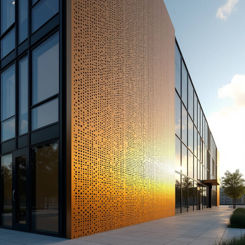
When a building envelope needs to do more than just enclose space—when it must manage solar gain, channel airflow, and still deliver a distinctive street presence—the conversation among facade engineers and procurement managers almost always turns to the Perforated Aluminum Facade. This is not a decorative afterthought. It is a precision-engineered skin where every hole diameter, pitch distance, and sheet gauge is calculated against wind loads, ventilation rates, and optical transparency targets. Getting the specification right means understanding what happens at the intersection of structural mechanics and material science. A 2.5mm or 3.0mm solid aluminium sheet, perforated with a specific open-area ratio and finished with a 30-micron minimum PVDF coating, behaves very differently from a solid panel under the same environmental conditions. The following analysis digs into the structural and performance logic that governs these systems, drawing on ASTM standards, published engineering data, and field experience from projects across Southeast Asia, the Middle East, and North America.
How Perforation Reshapes Structural Behavior in Solid Aluminium Panels
Start with a simple fact: a 3.0mm-thick solid aluminium sheet (Alloy 5052-H32 or 3003-H14) has a known modulus of elasticity of approximately 70.3 GPa and a yield strength in the range of 193 MPa for H32 temper. When you punch holes into that sheet, you are not just removing material—you are redistributing stress paths. The effective stiffness of a Perforated Aluminum Facade panel drops in a non-linear relationship with open-area ratio. A panel with 30% open area does not retain 70% of its original bending stiffness. Empirical data from bending tests on perforated aluminium sheets shows that stiffness reduction follows a curve that steepens beyond roughly 20% open area.
The practical implication for specifiers: if your design calls for a 40% open-area ratio to achieve a particular visual transparency or ventilation target, you cannot simply take the span tables for solid 3.0mm sheet and apply a 0.6 multiplier. The panel may need to go to a heavier gauge, or the sub-frame spacing must be tightened. This is where many value-engineering exercises go wrong. A contractor sees a perforated panel quote that is higher than expected and asks to reduce the sheet thickness from 3.0mm to 2.5mm without adjusting the supporting framework. The result is visible oil-canning under thermal cycling, or worse, permanent deformation under design wind load.
ASTM E330 testing on perforated aluminium panels provides a reliable baseline. For a typical panel measuring 1,200mm x 2,400mm with 25% open area (round holes, 60-degree staggered pattern), supported on four edges with a continuous aluminium extrusion frame, the allowable deflection under design wind load (L/60 for walls per AAMA 501.4) can be maintained with a 2.5mm sheet when the mullion spacing does not exceed 600mm centers. Push that spacing to 900mm, and the same panel requires 3.0mm material. These are not theoretical numbers—they come from test reports and field verification on projects where Futeng® has supplied perforated panel systems for high-wind coastal applications.
Open-Area Ratio: The Number That Drives Every Downstream Decision
Open-area ratio is the percentage of the panel surface that is void. It is the single most consequential parameter in a Perforated Aluminum Facade specification because it simultaneously controls four things: structural capacity, airflow, daylight transmission, and visual screening. Change the open-area ratio, and you change the entire performance profile of the facade.
Here is a reference table based on common perforation patterns used in architectural cladding:
| Hole Diameter (mm) | Pitch (mm) | Pattern | Open Area (%) | Typical Application | Min. Sheet Gauge (mm) |
|---|---|---|---|---|---|
| 6 | 10 | 60° Staggered | 32.7 | Ventilated rainscreen, parking garages | 2.5 |
| 8 | 14 | 60° Staggered | 29.6 | Solar shading over glazing | 2.5 |
| 10 | 20 | 60° Staggered | 22.7 | Privacy screens, stair towers | 2.0 |
| 12 | 18 | Straight Line | 34.9 | Double-skin outer layer | 3.0 |
| 16 | 24 | 60° Staggered | 40.3 | Decorative mesh effect, low wind zones | 3.0 |
| 20 | 35 | Straight Line | 25.6 | Brise-soleil, horizontal sun control | 2.5 |
These numbers are starting points. Each project requires its own wind load calculation. A 40% open-area panel on a 40-story tower in Manila faces a very different pressure regime than the same panel on a three-story office building in Stuttgart. The facade engineer's job is to run those numbers before the pattern is locked in, not after.
Wind Load: Why Perforated Panels Do Not Behave Like Solid Cladding
Solid aluminium cladding panels resist wind pressure primarily through bending stiffness distributed across a continuous surface. When wind hits a Perforated Aluminum Facade, some of the air passes through the holes. This reduces the net pressure on the panel face, but it also introduces a complicated partial-pressure scenario on the interior side of the panel, particularly in rainscreen applications where there is an air cavity behind the perforated skin.
The pressure equalization effect is real but not as dramatic as some manufacturers claim. Testing conducted in accordance with ASTM E330 shows that for open-area ratios below 20%, the reduction in net pressure is typically less than 10% compared to a solid panel. At 35% open area, the reduction can reach 20-25%, but this is highly dependent on cavity depth and venting configuration. A shallow cavity (less than 50mm) with restricted edge venting will not equalize effectively. A deep cavity (150mm or more) with open perimeter venting performs much better.
The critical failure mode to watch for is not outright panel rupture but fatigue at the hole edges. Each perforation creates a stress concentration. Under cyclic wind loading—which is the norm for any building over 20 meters tall—these stress concentrations can initiate micro-cracking if the sheet material is not properly specified. Alloy 5052-H32 is preferred over 3003-H14 for perforated applications specifically because of its superior fatigue resistance. The magnesium content in 5052 (approximately 2.5%) provides better work-hardening characteristics and higher ultimate tensile strength, which translates to longer service life under fluctuating loads.
For projects in hurricane-prone regions, the AAMA 501.4 test protocol for dynamic wind loading should be specified. This involves cycling the panel through 9,000 pressure cycles that simulate the lifespan of wind events. Perforated panels that pass this test with a 3.0mm 5052-H32 sheet and a properly engineered sub-frame will typically show no visible deformation and no fastener loosening.
Corrosion and Coating: The Hole Edge Problem
When you punch or drill holes through a PVDF-coated aluminium sheet, you create raw aluminium edges inside every hole. These edges have no coating. In a coastal or industrial environment, this is where corrosion starts. The standard solution is to apply the PVDF coating after perforation, but this is not always practical for large production runs or complex patterns. The alternative is to specify a pre-coated sheet with a chromate conversion coating pretreatment that extends into the hole edges, followed by a post-perforation touch-up process.
PVDF (polyvinylidene fluoride) coatings based on Kynar 500® or Hylar 5000® resin systems are the industry standard for architectural aluminium. The minimum total dry film thickness for exterior applications is 30 microns (1.2 mils) per AAMA 2605. For a Perforated Aluminum Facade, this specification should be explicitly stated in the coating section of the project manual, with a note that the coating applicator must verify coverage on hole interiors to the extent practical. Full coverage of hole interiors is not achievable with spray application, which is why the pretreatment step is critical.
For projects within 5 kilometers of a coastline or in heavy industrial zones, a marine-grade PVDF system with a minimum 40-micron total film thickness and a 10-micron primer layer is recommended. Some suppliers, including Futeng®, offer a modified PVDF formulation with enhanced corrosion inhibitors specifically for perforated panels destined for aggressive environments. The cost premium is approximately 12-15% over standard PVDF, but the alternative—edge corrosion appearing within 3-5 years—is far more expensive to remediate.
Thermal Movement and Sub-Frame Design
Aluminium expands at approximately 2.4mm per meter per 100°C of temperature change. A 3-meter-long perforated panel on a south-facing facade in Arizona can experience a surface temperature swing of 60°C between a cold winter morning and direct summer sun. That translates to roughly 4.3mm of linear expansion. If the panel is rigidly fixed at multiple points, it will buckle.
The sub-frame for a Perforated Aluminum Facade must accommodate this movement. The standard approach uses a combination of fixed points (typically two per panel, located near the center) and sliding points (all other connections). The sliding connections use elongated holes or slotted brackets that allow the panel to expand and contract freely. The perforation pattern itself can help—panels with higher open-area ratios have slightly lower effective thermal mass and may experience marginally reduced temperature extremes, but this effect is too small to rely on for movement accommodation.
The sub-frame material is almost always aluminium (Alloy 6063-T6 extrusions), which has a similar coefficient of thermal expansion to the panel material. Using steel sub-frames with aluminium panels creates a differential expansion problem that requires careful detailing of the connection points. Stainless steel fasteners (Grade 304 or 316) are standard, with nylon or EPDM washers to prevent galvanic contact between dissimilar metals.
Acoustic Performance: What Holes Do to Sound Transmission
A solid aluminium panel has a sound transmission class (STC) rating that depends primarily on its mass. A 3.0mm aluminium sheet weighs approximately 8.1 kg/m² and provides an STC of roughly 28-30 as a single leaf. When you perforate that sheet, the STC drops dramatically. At 20% open area, the STC can fall to 15 or lower. At 40% open area, the panel provides essentially no meaningful sound insulation.
This has implications for buildings near airports, highways, or industrial zones. A Perforated Aluminum Facade used as a rainscreen over a solid backing wall can still achieve good overall acoustic performance if the backing wall provides the primary sound barrier. But if the perforated panel is the only envelope element—as in a parking garage or an open-air circulation zone—the acoustic environment will be dominated by external noise.
For projects where acoustic performance matters, the solution is usually a composite assembly: a perforated outer skin, an air cavity with acoustic insulation (mineral wool, typically 50-100mm thick), and a solid inner lining. The perforated panel in this configuration acts as a protective and aesthetic layer while the insulation and inner lining handle the acoustics. The open-area ratio of the perforated panel should be at least 20% to avoid reflecting too much sound energy back into the cavity.
Cost Drivers That Procurement Teams Need to Understand
The cost of a Perforated Aluminum Facade system is driven by factors that are not always obvious from a unit-rate perspective. The raw material cost of the aluminium sheet is only one component. Here are the main cost drivers, ranked by their typical impact on the final installed price per square meter:
- Open-area ratio and hole count. A panel with 40% open area requires more punching time and generates more scrap than one with 20% open area. The relationship is not linear—very dense patterns with small holes take longer to punch than sparse patterns with large holes, even at the same open-area ratio.
- Sheet thickness. Moving from 2.0mm to 3.0mm adds approximately 50% to the material cost and increases handling weight, which affects installation labor and substructure requirements.
- Coating specification. Standard PVDF vs. marine-grade PVDF vs. anodized finish. Anodizing perforated panels adds complexity because the anodizing bath must circulate through all the holes uniformly.
- Panel size and aspect ratio. Larger panels reduce the number of joints and fasteners but increase the risk of handling damage and require thicker material to control deflection.
- Sub-frame complexity. A unitized system with factory-assembled panels and sub-frames costs more upfront but reduces site labor. Stick-built systems reverse that equation.
- Site access and logistics. Perforated panels are more susceptible to bending damage during transport than solid panels. Crating and handling costs can be 15-20% higher.
As a rough order-of-magnitude estimate, a standard Perforated Aluminum Facade system with 2.5mm 5052-H32 sheet, 25% open area, standard PVDF finish, and a simple aluminium sub-frame will land in the range of $180-$280 per square meter, supplied and installed, depending on region, project scale, and access conditions. Complex geometries, very high open-area ratios, or marine-grade finishes push this toward the upper end of the range or beyond.
Fabrication Tolerances and Quality Control
Perforated panels demand tighter fabrication tolerances than solid panels for one simple reason: the human eye is extremely sensitive to pattern irregularities. A 1mm deviation in hole position is invisible on a single panel, but when two adjacent panels are installed side by side and the pattern does not align, the mismatch is immediately obvious from 20 meters away.
The industry standard for perforation positioning tolerance is ±0.5mm for hole center locations relative to the panel datum. This requires CNC punching or laser cutting equipment with closed-loop positioning control. Manual punching or older NC equipment cannot reliably hold this tolerance across a full production run. For projects where pattern continuity across panel joints is critical—which is most architectural applications—the specification should require that panels be fabricated in their final installation sequence and that the perforation program be adjusted to account for the gap between panels.
Flatness after perforation is another quality control issue. The punching process releases residual stresses in the aluminium sheet, which can cause the panel to bow or twist. A flatness tolerance of 0.5% of the panel's diagonal dimension (per ASTM B209 for aluminium sheet) should be specified and verified after perforation, not before. Some bowing can be corrected through roller leveling, but this adds cost and may affect the coating if done after finishing.
At Futeng®, the quality control protocol for perforated panels includes a 100% visual inspection under controlled lighting, flatness measurement on a granite surface table for the first five panels of each production batch, and random sampling for hole diameter verification using go/no-go gauges. This level of QC is not unusual for suppliers serving the architectural market, but it should be explicitly required in the purchase specification rather than assumed.
Fire Performance and Code Compliance
Solid aluminium sheet is non-combustible. Perforating it does not change that. However, the overall fire performance of a Perforated Aluminum Facade assembly depends on the complete system, including the sub-frame, insulation, and any backing materials. The panel itself will achieve an A1 or A2-s1,d0 classification under EN 13501-1 when tested as a standalone product.
The more relevant fire concern for perforated facades is the behavior of the cavity behind the panel. In a rainscreen configuration, the air cavity can act as a chimney if not properly fire-stopped at floor levels. Building codes in most jurisdictions require horizontal fire barriers at each floor line and vertical fire barriers at specified intervals. The perforated panel itself does not provide any fire separation, so the fire engineering must assume that flames and hot gases can pass through the perforations.
For projects in jurisdictions that reference the NFPA 285 test standard for exterior wall assemblies, the complete facade system—including the perforated panel, air cavity, insulation, and backing wall—must be tested as an assembly. A perforated panel that passes a standalone combustibility test does not guarantee that the full assembly will pass NFPA 285. This is a common source of confusion during specification and should be clarified with the system supplier early in the design process.
Making the Specification Work: Practical Recommendations
After years of seeing perforated facade projects succeed and fail, a few patterns emerge. The projects that go smoothly share these characteristics:
The open-area ratio is locked in early, based on performance requirements (ventilation, daylight, screening) rather than aesthetic preference alone. The structural engineer has run the wind load calculations for the specific panel size, thickness, and open-area ratio before the shop drawings are started. The coating specification accounts for the uncoated hole edges, either through post-perforation coating or a robust pretreatment and touch-up protocol. The sub-frame design includes provision for thermal movement, with fixed and sliding points clearly identified on the drawings. And the fabrication tolerances are written into the purchase order, not assumed.
The projects that run into trouble almost always have one thing in common: the perforation pattern was treated as a purely architectural decision, with the engineering consequences addressed too late. A Perforated Aluminum Facade is an engineered system, not a decorative screen. The holes are structural features. They change how the panel handles wind, how it moves with temperature, how it corrodes over time, and how it performs in a fire. Treating them as such from the start of the design process is the difference between a facade that performs for 30 years and one that becomes a maintenance liability in five.
For procurement teams, the key takeaway is that the lowest bid on a perforated panel package often hides compromises in sheet thickness, coating quality, or fabrication tolerances that will surface as problems after installation. The specification should be detailed enough that all bidders are pricing the same thing. If one bid is 30% lower than the others, it is not because that supplier is more efficient—it is because they are quoting something different.