Perforated Aluminium Panel Structural Engineering for Rainscreen Facades
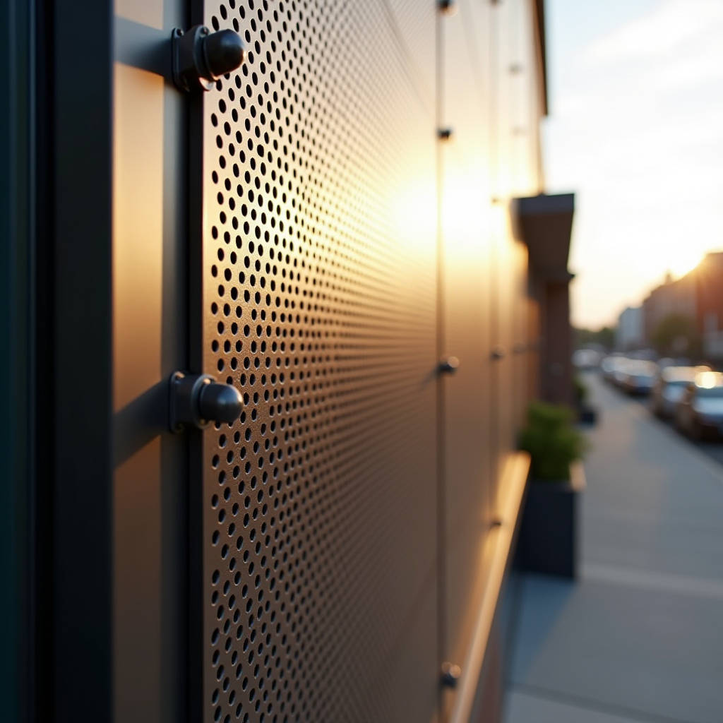
Specifying a Perforated Aluminium Panel for a rainscreen facade is not simply a matter of picking a hole pattern from a catalogue. The real engineering challenge lies in balancing open area percentage against wind load resistance, a tension that directly impacts panel gauge selection, fixing design, and long-term flatness. A panel with 35% open area looks striking on a render but behaves fundamentally differently under negative wind suction than a solid sheet. The holes relieve pressure, yes, but they also reduce the structural cross-section that resists bending. Getting this calculation wrong leads to oil-canning, excessive deflection, or fastener fatigue. This article unpacks the structural logic behind perforated cladding, covering how to calculate effective section properties, why hole layout orientation matters for spanning capability, and what your fixing engineer needs to know before the first panel leaves the factory floor.
How Perforation Reduces Effective Section Modulus
When you punch holes into a solid aluminium sheet, you remove material that would otherwise contribute to the panel's bending stiffness. The section modulus Z of a flat rectangular panel is directly proportional to its width and the square of its thickness. For a solid 3.0 mm thick panel spanning 600 mm between fixings, the calculation is straightforward. But once you introduce perforations, the effective width of the cross-section shrinks.
The standard approach is to calculate the ligament efficiency, defined as the ratio of solid material remaining between holes along the critical bending axis. For a staggered hole pattern with 6 mm diameter holes at 10 mm pitch, the ligament between adjacent holes is 4 mm. If you take a unit width of 100 mm, you have roughly 10 holes, meaning 60 mm of that width is void and 40 mm remains solid. The ligament efficiency is 0.40. This means the effective section modulus drops to approximately 40% of the solid panel value.
This reduction has a cascading effect. A panel that comfortably spans 600 mm in solid form at L/180 deflection limits might need to be reduced to 400 mm centres once perforated. Alternatively, you increase the gauge. A 3.0 mm perforated panel with 40% ligament efficiency has roughly the same bending stiffness as a 1.9 mm solid panel of the same alloy. Many specifiers default to 2.5 mm or 3.0 mm gauges for perforated work precisely because they are compensating for this loss, not because they need the material for corrosion allowance.
Open Area Percentage and Wind Pressure Relief
The open area percentage of a Perforated Aluminium Panel is the ratio of total hole area to total panel area, expressed as a percentage. Common architectural specifications range from 15% to 40%, though some decorative screens push beyond 50%. The structural implication is twofold: reduced wind load on the panel itself, and reduced load transfer to the substructure.
A panel with 30% open area does not experience 30% less wind pressure. The relationship is non-linear. Wind tunnel studies and the guidance in EN 1991-1-4 and AS/NZS 1170.2 indicate that the pressure coefficient for a perforated surface depends on the porosity. At 20% open area, the pressure reduction might be 15-25%. At 40% open area, the reduction can reach 40-50%. However, the standard also requires that you account for the possibility of holes becoming blocked by debris, ice, or maintenance oversights. Many conservative engineers apply a blockage factor of 50% to 75%, meaning they assume only half to three-quarters of the holes are actually functioning as pressure relief at any given time.
The practical takeaway: do not rely on hole porosity to downsize your substructure. Design the supporting framework as if the panel were solid, then treat the porosity as an additional safety margin. This approach aligns with the guidance from the American Architectural Manufacturers Association (AAMA) on rainscreen design principles.
Hole Pattern Orientation and Span Direction
Not all perforation patterns are isotropic. A square grid of round holes at equal pitch in both directions gives roughly equal stiffness reduction in both axes. But a rectangular pitch, or a slot pattern oriented parallel to the span, behaves very differently depending on which way the panel is installed.
Consider a panel with 4 mm x 20 mm slots at 8 mm longitudinal pitch and 12 mm transverse pitch. If the slots run parallel to the span direction, the longitudinal ligament is 4 mm between slot ends, and the transverse ligament is the full 12 mm between slot rows. The panel is significantly stiffer in the transverse direction. If you install this panel with the slots running perpendicular to the span, the bending axis sees the 12 mm transverse ligament as the effective solid width, which is much better. But if the slots run parallel to the span, the bending axis cuts through the 4 mm end ligaments, and the panel is far more flexible.
This is not a minor detail. A misoriented slot pattern can reduce effective stiffness by an additional 30-50% compared to the same panel installed correctly. The specification drawing should always include a note indicating the required orientation of the perforation pattern relative to the fixing rails. Where possible, specify a staggered round hole pattern at equal pitch; it eliminates the orientation variable and simplifies the structural check.
Alloy Selection for Punched Panels
Not all aluminium alloys respond to punching the same way. The three most common alloys for architectural Perforated Aluminium Panel work are 3003, 5052, and 6061, each with distinct characteristics relevant to perforated applications.
| Alloy | Temper | Yield Strength (MPa) | Elongation (%) | Perforation Suitability | Typical Application |
|---|---|---|---|---|---|
| 3003 | H14 | 145 | 8-16 | Excellent – soft, minimal burr | Interior screens, decorative panels |
| 5052 | H32 | 195 | 7-12 | Very good – moderate tool wear | Exterior rainscreens, marine environments |
| 6061 | T6 | 240 | 8-10 | Fair – higher tool wear, burr tendency | High-stress structural screens |
Alloy 3003-H14 punches cleanly and is the most forgiving for intricate hole patterns. However, its lower yield strength means you may need to go up a gauge compared to 5052. For exterior applications within 3 km of a coastline, 5052-H32 is the preferred choice due to its superior corrosion resistance in saline environments. The magnesium content in 5052 provides better resistance to pitting than the manganese-only 3003 series. 6061-T6 offers the highest strength but is harder on tooling, and the punched edges can exhibit micro-cracking if the tool clearance is not precisely maintained. For most architectural cladding, 5052-H32 at 2.5 mm or 3.0 mm gauge strikes the right balance between formability, corrosion resistance, and post-punching flatness.
Flatness Tolerance After Perforation
Punching introduces residual stresses into the sheet. As each punch penetrates, it displaces material, creating a slight compressive zone around the hole perimeter. When thousands of holes are punched across a panel, these residual stresses accumulate and can cause the panel to bow or twist. This is not a material defect; it is a predictable consequence of the manufacturing process.
The industry standard for flatness on perforated sheets is typically looser than for solid sheets. ASTM International does not publish a dedicated flatness standard for perforated aluminium, but the general tolerance for aluminium sheet flatness per ASTM B209 is often used as a reference, with an understanding that some deviation is inherent. A practical specification for a 1,220 mm x 2,440 mm perforated panel might allow 3-4 mm of bow across the diagonal, compared to 1-2 mm for a solid panel of the same size.
There are several ways to mitigate post-punch flatness issues. Tension levelling after perforation is effective but adds cost. Specifying a thicker gauge reduces the relative impact of residual stresses. Using a staggered hole pattern rather than a straight-line pattern distributes the stresses more evenly. And if the panel is being folded into a cassette or tray, the fold lines themselves act as stiffeners that pull the panel flat. For flat panels installed without edge folds, flatness must be addressed at the specification stage, not discovered on site when the sun angle reveals every ripple. Suppliers such as Futeng® with dedicated perforation lines often include a flattening pass as part of their standard process for architectural-grade panels, which is worth confirming during the technical submittal review.
Fixing Design for Perforated Panels
The fixing system for a Perforated Aluminium Panel must account for the fact that the bearing area around each fastener hole is reduced by nearby perforations. A standard M6 stainless steel rivet or screw has a head diameter of approximately 12-14 mm. If the fixing hole is located such that a perforation lies within 5 mm of the fixing hole edge, the effective bearing area is compromised, and the risk of tear-out under wind load increases substantially.
The rule of thumb: maintain a minimum distance of 2.5 times the perforation hole diameter between the edge of any perforation and the edge of any fixing hole. For a panel with 8 mm diameter perforations, that means a 20 mm clear zone around each fixing point. This should be detailed on the fabrication drawing, and the perforation pattern should be designed to accommodate these clear zones. In some cases, the panel perimeter is left unperforated for a 30-50 mm border specifically to provide a solid fixing zone.
The fixing type also matters. For panels with open areas above 30%, the wind pressure on the panel is partially relieved, but the fixing itself is still exposed to the full pressure differential. Stainless steel fasteners with a minimum grade of A2-70 (304) or A4-70 (316 for coastal) are standard. The fastener should be sized so that the pull-through capacity of the head through the aluminium sheet exceeds the design wind load by a factor of at least 2.0. This is particularly critical for thin-gauge perforated panels where the remaining solid material around the fastener is limited.
Acoustic Performance and Perforation
Perforated aluminium panels can contribute to acoustic management, but the mechanism is often misunderstood. A perforated panel by itself does not absorb sound; it allows sound waves to pass through to an acoustic backing layer. The panel acts as a protective and decorative face for mineral wool, fibreglass, or acoustic foam behind it.
The acoustic transparency of a perforated panel depends on the open area percentage and the hole diameter relative to the wavelength of the sound frequencies of interest. For speech-range frequencies (500 Hz to 4,000 Hz), a panel with 20% or greater open area and hole diameters of 3-6 mm will be largely acoustically transparent, meaning the sound absorption performance is determined almost entirely by the backing material, not the panel itself. Below 15% open area, the panel starts to reflect a significant portion of incident sound energy.
For projects where acoustic performance is a primary requirement, the specification should reference the sound absorption coefficient testing per ISO 354 or ASTM C423. The test data should be for the complete assembly (panel plus backing), not for the panel alone. A common specification for parking garage screens or plant room enclosures is a Noise Reduction Coefficient (NRC) of 0.75 or higher, which is achievable with a 25% open area perforated panel over 50 mm thick mineral wool of 48 kg/m³ density.
Coating Systems for Perforated Surfaces
Applying a PVDF or powder coating to a perforated panel presents challenges that do not exist with solid panels. The edges of each perforation hole must be coated to prevent corrosion initiation, but the coating thickness on hole edges is typically thinner than on the flat surface. This is because electrostatic spray application relies on the Faraday cage effect, and the interior of small holes can repel charged powder particles.
For PVDF (polyvinylidene fluoride) coatings conforming to AAMA 2605, the specification should require a minimum of 30 microns dry film thickness on the flat surface, with an acknowledgement that hole edges may achieve 20-25 microns. The coating applicator should adjust gun settings and line speed to maximise penetration into the holes. For panels with hole diameters below 5 mm, powder coating may struggle to achieve adequate edge coverage, and a liquid PVDF system is generally preferred.
Anodising is an alternative for perforated panels, and it has the advantage of being a conversion coating that grows from the aluminium surface itself, meaning hole edges receive the same coating thickness as flat surfaces. However, anodised finishes are limited in colour range and are more susceptible to staining from mortar or acidic rain. For most architectural exterior applications, a three-coat PVDF system (primer, colour coat, clear coat) over a chromate conversion coating pretreatment provides the best balance of durability and aesthetic consistency.
Cost Drivers in Perforated Panel Specification
The cost of a Perforated Aluminium Panel is driven by several factors beyond the base material price. Understanding these allows the specifier to make informed trade-offs without compromising performance.
- Open area percentage: Higher open area means more punch strokes, longer machine time, and more tool wear. A panel with 40% open area can cost 25-35% more than one with 20% open area from the same material.
- Hole diameter: Smaller holes require more punches per square metre. A panel with 3 mm holes at 6 mm pitch has roughly 27,800 holes per square metre. The same panel with 8 mm holes at 16 mm pitch has about 3,900 holes per square metre. The tooling cost and cycle time difference is substantial.
- Pattern complexity: A standard staggered round hole pattern is the most economical. Custom patterns, logos, or variable-density perforations require custom tooling, programming, and longer run times.
- Alloy and gauge: 5052 costs more than 3003. 3.0 mm gauge costs more than 2.0 mm. These are straightforward material cost multipliers.
- Border zones: Panels with unperforated borders require the punch program to stop short of the edge, which can slow production if the pattern does not align neatly with the panel dimensions.
For budget-sensitive projects, specifying a standard round hole pattern in 3003-H14 at 2.5 mm gauge with 20-25% open area and a PVDF two-coat finish will deliver a durable, attractive result at the lower end of the cost spectrum. Adding complexity in any of the above dimensions will increase the square-metre rate, and the cost curve is steeper than many project teams anticipate.
Site Handling and Installation Considerations
Perforated panels are more susceptible to handling damage than solid panels. The reduced cross-section means that a panel lifted by one corner can bend or crease more easily. The holes also create stress concentration points; a sharp impact near a hole is more likely to initiate a tear than the same impact on a solid sheet.
Installation teams should be briefed on the following:
- Panels should be stored flat on A-frames or on timber battens with protective interleaving. Never store perforated panels vertically leaning against a wall, as the self-weight can cause permanent bowing.
- Lifting should be done with vacuum lifters where possible, or with slings that distribute the load across the full panel width. Single-point lifting is unacceptable.
- Cutting on site should be minimised. If field modifications are required, a nibbler or shear is preferred over an angle grinder, which generates heat and can damage the coating around the cut edge.
- Any site-drilled holes for secondary fixings must be deburred and the exposed aluminium edge treated with a touch-up coating system approved by the panel manufacturer.
The fixing tolerance for perforated panels should be slightly more generous than for solid panels. A ±3 mm tolerance on the panel-to-panel gap is reasonable, compared to ±2 mm for solid panels, because the perforated edge is visually softer and small variations are less noticeable. This is not an excuse for sloppy installation, but it is a practical recognition of the material's behaviour.
Specifying Perforated Aluminium for Rainscreen Applications
When a Perforated Aluminium Panel is used as the outer skin of a rainscreen, the cavity behind the panel is directly exposed to the external environment through the perforations. This changes the cavity ventilation dynamics compared to a closed-joint solid panel rainscreen. The cavity behind a perforated panel will experience higher airflow, which improves drying but also means the cavity is wetter during rain events.
The design implications are significant. The supporting framework, brackets, and insulation must be suitable for exposure to driven rain. Stainless steel brackets and fixings are mandatory, not optional. The insulation should be a rigid mineral wool board with a black glass veil facing, not a foil-faced product that would be visible through the perforations and degrade under UV exposure. The cavity depth should be a minimum of 38 mm, but 50 mm is preferable to allow adequate drainage and ventilation behind the panel.
The perforated panel itself acts as a screen, but it is not a waterproof barrier. The building envelope must be fully sealed at the sheathing board or structural wall level. The rainscreen is exactly that: a screen that sheds the bulk of the rain but does not replace the air and water barrier. This is a fundamental rainscreen principle, but it is worth reiterating because the visual openness of a perforated panel can create a false impression that the panel is doing more weather protection work than it actually is.
For projects where the perforated panel is specified over glazing or vision areas, the visual impact from the interior must be considered. A 30% open area panel placed 150 mm in front of a window will reduce the visible light transmittance, but the pattern can also create a moiré effect if the hole spacing interacts with the mullion spacing of the curtain wall. A mock-up at full scale is strongly recommended before finalising the hole pattern for these applications.
Structural engineering for perforated rainscreens is a discipline that rewards careful calculation over rules of thumb. The panel gauge, alloy, hole pattern, fixing layout, and substructure design are all interconnected variables. Changing one without checking the others is the most common source of on-site problems. When the engineering is done properly, a Perforated Aluminium Panel rainscreen delivers decades of service with minimal maintenance, combining the practical benefits of screening and ventilation with the aesthetic flexibility that solid panels cannot match.