Solid Aluminum Facade Panel Thickness Engineering Guide for Wind Load Performance
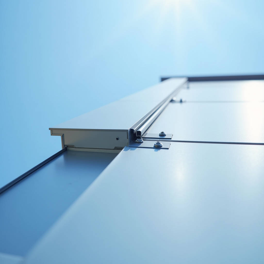
When a commercial high-rise in Chicago started shedding panels during a January windstorm, the investigation pointed to one root cause: the original 2.0 mm aluminum skins had been specified without accounting for the building's corner-zone negative pressures. The replacement spec called for 3.0 mm solid aluminum facade panels with engineered stiffener grids — and the building has weathered five winters since without incident. This is not a theoretical discussion. Panel thickness on a Solid Aluminum Facade is a structural decision that determines whether a building envelope performs or fails over a 30-year service life. The question is not simply "2.5 mm or 3.0 mm." It involves wind load calculations, panel aspect ratios, stiffener placement, folded edge geometry, and the specific alloy temper being used. This article examines how to make that decision with engineering rigor rather than rule-of-thumb guesswork.
Why Panel Thickness Is a Structural Decision, Not an Aesthetic One
Architects often treat panel thickness as a visual concern — will the facade read as flat and monolithic, or will oil-canning distortions appear under raking light? This framing misses the point. The thickness of a solid aluminum facade panel is fundamentally a structural parameter that governs how the panel behaves under wind suction, thermal cycling, and impact loading.
A 2.5 mm panel fabricated from 3003-H14 alloy and installed as a 1,200 mm × 3,000 mm flat sheet with 25 mm folded returns will deflect differently than a 3.0 mm panel of identical geometry. The difference is not linear. Deflection under uniform load follows a relationship proportional to the cube of the thickness — meaning a 3.0 mm panel is roughly 73% stiffer than a 2.5 mm panel of the same alloy and dimensions, all else being equal. This has direct consequences for wind load resistance, fastener fatigue, and long-term flatness retention.
What complicates matters is that thickness alone does not tell the full story. Panel geometry, stiffener design, alloy selection, and fixing method all interact with thickness to determine actual performance. A well-engineered 2.5 mm panel with properly spaced stiffeners can outperform a poorly detailed 3.0 mm panel. The key is understanding how these variables combine.
Reading Wind Loads: From ASCE 7 to Panel Deflection Limits
Wind load governs panel thickness selection for most mid-rise and high-rise projects. The starting point is the design wind pressure, typically calculated per ASCE 7 in North America, EN 1991-1-4 in Europe, or local building codes elsewhere. For a solid aluminum facade, the critical parameter is not the average zone pressure but the peak negative pressure at corner zones, where wind suction can be 2.5 to 3 times higher than the field zone.
Consider a 60-meter building in Exposure Category B. Corner zone design pressures might reach 2.4 kPa under ultimate wind conditions. A 2.5 mm panel spanning 1,200 mm between stiffeners might deflect 8-10 mm under this load, which could exceed the typical L/60 deflection limit (20 mm for a 1,200 mm span) but may still be within allowable stress limits. The question is whether the deflection is acceptable for the specific coating system and visual requirements.
For serviceability (non-factored) wind loads, many specifications require deflection not to exceed L/90 or even L/120 for premium architectural finishes. At L/120, a 1,200 mm span allows only 10 mm of deflection. A 2.5 mm panel may struggle to meet this criterion without additional stiffeners, while a 3.0 mm panel typically passes comfortably. The cost difference between adding stiffeners versus upgrading to 3.0 mm material should be evaluated on a project-specific basis.
Per AAMA 508-14, "Voluntary Specification for Expanded Aluminum," panel deflection under design wind load shall not exceed L/60 for the span between supports, and permanent deformation after load removal shall not exceed 0.2% of the span. AAMA standards provide the baseline; many project specifications tighten these limits further.
Alloy Selection: 1100, 3003, and 5052 Compared
Not all aluminum is equal when formed into facade panels. The three alloys most commonly encountered in solid aluminum facade applications are 1100, 3003, and 5052. Each brings different mechanical properties, forming characteristics, and corrosion resistance profiles to the table.
| Alloy & Temper | Tensile Strength (MPa) | Yield Strength (MPa) | Elongation (%) | Typical Facade Application |
|---|---|---|---|---|
| 1100-H14 | 110-145 | 95-125 | 3-9 | Low-rise, small panel sizes, flat applications |
| 3003-H14 | 150-200 | 145-185 | 1-8 | General architectural cladding, most common |
| 5052-H32 | 230-280 | 195-245 | 4-12 | High-wind zones, marine environments, curved panels |
3003-H14 is the workhorse of the solid aluminum facade industry. It offers a balanced combination of formability, strength, and cost. For projects in coastal or high-corrosion environments, 5052-H32 provides superior salt-spray resistance and higher strength, allowing potentially thinner gauges to achieve equivalent structural performance — though the material cost premium runs 15-25% over 3003.
1100-H14, while the most formable, has lower strength and is generally reserved for interior applications or small decorative elements where structural demands are minimal. Specifying 1100 for exterior facade panels above 600 mm in any dimension is generally inadvisable without rigorous engineering review.
Stiffener Design: The Real Determinant of Panel Performance
Stiffeners are the hidden engineering that makes a solid aluminum facade work. A panel without stiffeners relies entirely on its own bending stiffness, which drops rapidly as span increases. Adding stiffeners changes the effective span, reducing deflection and stress proportionally.
The standard stiffener for solid aluminum panels is an extruded aluminum hat section, typically 25 mm × 40 mm or 30 mm × 50 mm, bonded to the panel back with structural adhesive. The stiffener spacing is determined by the allowable deflection for the given panel thickness and design wind load. For a 3.0 mm panel under 2.0 kPa wind load, stiffener spacing of 600-800 mm typically achieves L/90 deflection. For 2.5 mm panels, spacing may need to tighten to 400-600 mm.
Two critical details often overlooked in stiffener design:
- Thermal expansion compatibility: The stiffener material should match the panel alloy to avoid differential expansion stresses. Using 6063-T5 extruded stiffeners with 3003-H14 panels introduces a thermal expansion mismatch of approximately 2.4 × 10⁻⁶ /°C, which can cause adhesive bond line stress over decades of thermal cycling.
- Adhesive selection: Structural silicone or two-part epoxy adhesives must maintain bond strength across the full temperature range the facade will experience, typically -30°C to +80°C for most climates. Peel strength, not just shear strength, governs performance at the stiffener-to-panel interface.
Futeng® has developed standard stiffener spacing tables based on decades of project data across multiple climate zones, which can serve as a starting reference for specification. However, project-specific engineering calculations should always govern final stiffener design.
Folded Edge Geometry and Its Contribution to Panel Stiffness
The folded return edge on a solid aluminum facade panel is not merely a detail for attachment — it contributes significantly to panel stiffness. A 25 mm folded edge on all four sides creates a shallow tray that resists bending through edge restraint. Increasing the fold depth to 35 mm or 40 mm can improve panel stiffness by 15-25%, sometimes allowing a thinner base material to achieve equivalent deflection performance.
The trade-off is in fabrication. Deeper folds require more material in the developed blank, increasing material cost. They also require larger bending radii to avoid cracking at the fold line, particularly with 3003-H14 material where the minimum inside bend radius is typically 1.5 times the material thickness. For a 3.0 mm panel, this means a 4.5 mm minimum inside radius, which must be accounted for in the panel's visual face dimensions.
For panels with two-way curves or complex geometries, fold depth may be limited by the forming process. CNC folding machines can handle up to approximately 40 mm folds on standard panels, but beyond this, specialized tooling or segmented bending may be required, adding cost and lead time.
Coating Systems and Thickness Interaction
The coating system on a solid aluminum facade does more than provide color. PVDF (polyvinylidene fluoride) coatings, typically applied at 25-35 microns dry film thickness for two-coat systems and 35-45 microns for three-coat metallic finishes, contribute to the panel's overall environmental resistance. The interaction between coating and substrate thickness matters for two reasons.
First, thinner panels deflect more under thermal load, and the coating must accommodate this movement without cracking or delamination. PVDF coatings are formulated for elongation of 100-200%, which is generally sufficient for the strains experienced by 2.5 mm and 3.0 mm panels under normal conditions. However, at panel edges and around stiffener bond lines where stress concentrations occur, the coating's elongation capacity can be exceeded if the panel is too thin and deflects excessively.
Second, the coating's solar reflectance affects panel temperature. Dark-colored panels in direct sun can reach 80°C or higher, while light-colored panels may stay below 50°C. This 30°C differential translates to approximately 0.7 mm/m of thermal expansion difference. Thicker panels, with their greater thermal mass, heat up and cool down more slowly, reducing the rate of thermal cycling but not the total expansion magnitude.
For reference, The Aluminum Association publishes thermal expansion coefficients for common aluminum alloys. The coefficient for 3003 alloy is 23.2 × 10⁻⁶ /°C, meaning a 3-meter panel experiences approximately 2.1 mm of expansion for every 30°C temperature change. The panel attachment system must accommodate this movement.
Attachment Systems: Cassette, Tray, and Hook-On Methods
How a solid aluminum facade panel is attached to the building substructure directly influences the effective thickness required. Three primary attachment methods dominate the market:
Cassette Systems
Cassette panels are fabricated as shallow trays with folded returns on all four edges. They typically hang on aluminum rails using a hook-and-lock mechanism. The folded edges provide continuous edge support, which reduces the effective span and allows thinner material. A 2.5 mm cassette panel with 30 mm returns and 600 mm stiffener spacing can perform similarly to a 3.0 mm panel with 25 mm returns and 800 mm spacing. The cassette system's inherent edge restraint is its primary structural advantage.
Tray Panels with Exposed Fasteners
Tray panels are simpler, with folded returns on four sides and visible mechanical fasteners through the face or returns. Because the fasteners are exposed, the panel is typically supported only at discrete points rather than continuously along edges. This reduces the effective edge restraint and may require thicker material or tighter stiffener spacing. A 3.0 mm panel is strongly recommended for tray systems with fastener spacing exceeding 400 mm.
Hook-On Systems
Hook-on panels use a continuous aluminum extrusion on the back of the panel that engages with a matching rail on the substructure. This system provides continuous vertical support but may leave horizontal edges free. The panel thickness must be sufficient to prevent buckling between horizontal supports. For standard 3,000 mm panel heights, 3.0 mm material is the practical minimum for hook-on systems without intermediate horizontal stiffeners.
The choice of attachment system should be made concurrently with thickness selection, not as a separate decision. A specification that calls out "2.5 mm solid aluminum panels" without defining the attachment method is incomplete and risks underperformance.
Cost Implications: The Real Numbers Behind Thickness Decisions
Material cost is the most visible factor in thickness selection, but it is not the only one. A comprehensive cost analysis must include fabrication, stiffeners, freight, and installation.
| Cost Factor | 2.5 mm Panel | 3.0 mm Panel | Delta |
|---|---|---|---|
| Raw material (per m²) | Base | +18-22% | Material weight increase |
| Stiffener requirements | Tighter spacing (400-600 mm) | Wider spacing (600-800 mm) | Stiffener cost may offset |
| Freight (per m²) | Base | +15-20% | Weight-dependent |
| Installation labor | More stiffeners = more handling | Fewer stiffeners, heavier panels | Roughly equivalent |
| Long-term warranty risk | Higher deflection, more claims | Lower deflection, fewer claims | Difficult to quantify |
The raw material cost increase from 2.5 mm to 3.0 mm is approximately 20% for the aluminum sheet alone. However, when stiffener savings are factored in — a 3.0 mm panel may require 30% fewer linear meters of stiffener extrusion — the net system cost increase often narrows to 8-12%. For projects where wind loads are high or panel dimensions are large, the 3.0 mm option frequently delivers better value when total installed cost and long-term performance are considered together.
For procurement managers, the key takeaway is to request quotations that include the full stiffener and attachment system, not just the panel material. A 2.5 mm panel quote that omits the additional stiffeners required to meet deflection criteria is not directly comparable to a 3.0 mm panel quote that includes fewer stiffeners.
Quality Verification: What to Inspect Before Shipment
Specifying the correct thickness is only half the equation. Verifying that the delivered panels match the specification requires systematic inspection. Key checkpoints include:
- Material certification: Request mill test certificates (MTCs) that verify alloy grade, temper, and actual thickness. The tolerance for sheet thickness per ASTM B209 is ±0.08 mm for 2.5 mm sheet and ±0.10 mm for 3.0 mm sheet. Panels at the lower end of the tolerance band may not meet deflection requirements.
- Coating thickness measurement: PVDF dry film thickness should be verified with a calibrated eddy-current gauge per ASTM D7091. Minimum 25 microns for two-coat, 35 microns for three-coat systems.
- Flatness inspection: Panels should be checked on a flat inspection table under standardized lighting. Oil-canning (visible waviness) is assessed per AAMA 508-14. While some oil-canning is inherent to flat sheet metal, excessive waviness indicates either insufficient thickness, inadequate stiffening, or residual stresses from fabrication.
- Adhesive bond testing: For stiffened panels, pull-off testing of the adhesive bond should be conducted on sample panels from each production batch. A minimum bond strength of 1.0 MPa is typical for structural silicone systems.
Making the Final Call: A Decision Framework
Given all the variables — wind loads, panel dimensions, alloy, stiffeners, attachment method, coating, and budget — how should a project team decide between 2.5 mm and 3.0 mm solid aluminum facade panels? The following decision framework provides a structured approach:
- Start with wind load: Calculate design pressures per the applicable code. If corner zone pressures exceed 2.0 kPa, lean toward 3.0 mm.
- Check panel dimensions: For panels with any dimension exceeding 2,400 mm, 3.0 mm provides a meaningful stiffness advantage. For panels under 1,200 mm in both dimensions, 2.5 mm may be adequate with proper stiffening.
- Evaluate the attachment system: Cassette systems with continuous edge support can work with 2.5 mm. Tray systems with discrete fasteners benefit from 3.0 mm.
- Consider the environment: Marine or high-corrosion environments favor 5052 alloy, which may allow 2.5 mm to perform where 3003 at 3.0 mm would be required. Coastal projects should specify 5052-H32 regardless of thickness.
- Factor in the coating: Dark-colored PVDF finishes on large panels in hot climates experience greater thermal movement. The additional stiffness of 3.0 mm helps maintain flatness through thermal cycles.
- Run the total cost: Compare full system costs including stiffeners, not just material costs. The 3.0 mm option often narrows the gap significantly when stiffener savings are included.
- Check warranty requirements: Some coating suppliers require minimum substrate thicknesses for their extended warranties. Verify before finalizing the specification.
The decision between 2.5 mm and 3.0 mm solid aluminum facade panels is not a matter of "better" or "worse." It is a matter of matching the engineering to the specific demands of the project. The Chicago high-rise that failed with 2.0 mm panels now performs reliably with 3.0 mm panels because the engineering was done properly the second time. Doing it properly the first time costs less than re-cladding a building — and costs far less than the reputational damage of a facade failure.