Perforated Aluminium Facade Engineering Guide for Solid Panel Rainscreen Systems
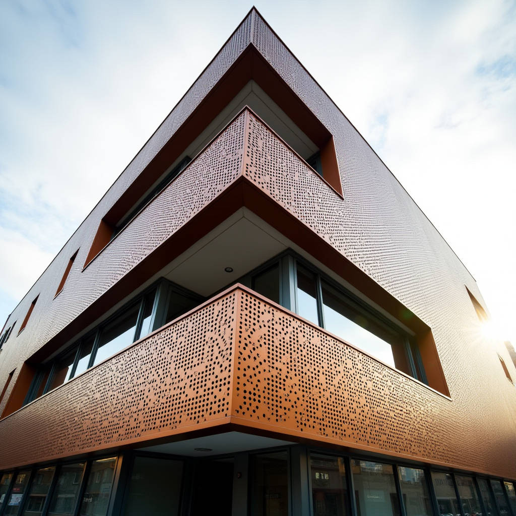
A perforated aluminium facade does more than dress a building. It filters daylight, cuts solar gain, and pulls fresh air across a cavity — all while shielding the internal structure from direct rain. For contractors and facade engineers, specifying perforated solid aluminium panels means balancing open-area ratios against structural stiffness, corrosion resistance, and long-term flatness. This article breaks down the engineering logic behind hole geometry, wind load behaviour, drainage detailing, and PVDF coating integrity on perforated 2.5mm and 3.0mm solid aluminium sheets. If you are pricing a ventilated rainscreen or a double-skin envelope, the calculations here will help you lock down the technical parameters before the shop drawings begin.
Why Perforation Changes the Engineering Game
Solid aluminium cladding panels behave predictably under uniform load. Once you punch holes through the sheet, three things shift at once. First, the effective section modulus drops because material is removed from the cross-section. Second, stress concentrations appear around each perforation edge. Third, the panel's natural frequency changes, which matters for tall-building facades where vortex shedding can excite lightweight cladding.
A 2.5mm thick EN AW-5754 (AlMg3) solid aluminium sheet with 20% open area loses roughly 15–18% of its bending stiffness compared to an unperforated sheet of the same gauge, based on finite element studies conducted by the American Architectural Manufacturers Association (AAMA). At 40% open area, stiffness can drop by 30% or more. This means the substructure spacing often needs to tighten from 600mm centres to 400mm or even 350mm centres, depending on the design wind pressure. Engineers who treat perforated panels as if they were solid sheets will see oil-canning, fastener fatigue, and water ingress within the first two years.
For a typical 30-metre office tower in a suburban exposure category, design wind pressure might sit around 1.5 kPa. A solid 3.0mm aluminium panel spanning 600mm between aluminium T-profiles will deflect well within the L/60 serviceability limit. That same panel with a staggered 8mm round-hole pattern at 35% open area may need span reduction to 450mm to stay under the deflection limit. The extra framing adds roughly 12–18% to the substructure cost per square metre, but skipping that step costs far more in remedial work.
Open-Area Ratio: The Number That Drives Everything
Open-area ratio is the percentage of the panel surface that is void. It governs ventilation, solar shading, visibility, and structural capacity. Architects tend to push for higher ratios to achieve transparency and airflow. Structural engineers push back because every percentage point above 25% starts eating into the panel's ability to carry wind load without excessive deflection.
Here is a practical breakdown of how open-area ratios map to engineering decisions for solid aluminium perforated panels:
| Open-Area Ratio | Typical Application | Recommended Min. Sheet Thickness | Typical Substructure Span | Wind Load Capacity Note |
|---|---|---|---|---|
| 10–15% | Visual texture, mild shading | 2.0mm | 600mm | Near-solid panel behaviour |
| 15–25% | Solar screening, partial privacy | 2.5mm | 500–550mm | Moderate stiffness reduction |
| 25–35% | Ventilated rainscreen, acoustic backing | 2.5–3.0mm | 400–450mm | Significant stiffness loss; check deflection |
| 35–50% | Double-skin outer layer, parking screens | 3.0mm | 350–400mm | Requires FEA verification per project |
| 50%+ | Decorative mesh-like facades | 3.0mm minimum | 300–350mm | Often needs stiffener ribs or folded edges |
These figures are based on solid aluminium sheets conforming to EN 485-2 tolerances. Composite panels behave differently and are outside the scope of this discussion. When a project specifies perforated aluminium facade panels, the structural submittal must include panel-by-panel deflection calculations that account for the actual hole layout, not just an averaged open-area percentage. The hole pattern — staggered versus grid — also affects the stress distribution.
Hole Geometry: Round, Slot, or Custom
The shape of the perforation matters as much as the ratio. Round holes distribute stress more evenly than square or rectangular cutouts. A 10mm diameter round hole creates a stress concentration factor of roughly 2.5 at the hole edge under uniaxial tension. A square hole of equivalent side length pushes that factor above 3.0, and the corners become crack initiation points if the panel experiences cyclic wind loading over years.
Slot-shaped perforations — long narrow openings — are popular for linear architectural effects, but they introduce anisotropic stiffness. A panel with horizontal slots will be stiffer in the vertical direction and more flexible horizontally. This has to be accounted for in the fixing layout. The longer dimension of the slot should ideally run parallel to the main spanning direction of the panel, or the engineer must add intermediate fixings to control deflection.
Edge distance — the solid material between the outermost hole and the panel edge — is another detail that separates competent shop drawings from problematic ones. A minimum edge distance of 1.5 times the hole diameter is standard practice. For a 12mm hole, that means 18mm of solid material from the hole centre to the folded return edge. Tighter edge distances risk tearing during punching and create weak points that can propagate cracks under thermal cycling.
Coating Perforated Panels: The PVDF Challenge
Coating a solid aluminium sheet is straightforward. Coating a perforated sheet is not. The holes create hundreds or thousands of internal edges that must be covered to prevent filiform corrosion. PVDF (polyvinylidene fluoride) coatings — typically 70% PVDF resin with 30% acrylic or polyester modifiers — are the industry standard for architectural aluminium facades. The specification usually calls for a minimum 25-micron dry film thickness on flat surfaces, tested per AAMA 2605.
On a perforated panel, the coating must wrap into each hole and cover the interior wall of the perforation. If the liquid coating does not flow into the holes evenly, the cut edges inside each perforation remain exposed. Over time, moisture wicks into those uncoated edges and corrosion creeps outward under the paint film. This is filiform corrosion, and it is the most common failure mode on perforated aluminium facade panels installed in coastal or high-humidity environments.
The solution is a combination of proper pretreatment and application technique. A chrome-phosphate conversion coating applied by immersion — not spray — ensures the entire surface, including hole interiors, receives the pretreatment. Then, a PVDF spray system with electrostatic assistance can draw coating into the perforations. Some manufacturers, including Futeng®, run a two-stage spray process for perforated panels: a base coat applied from both sides, followed by a topcoat that seals the edges. The result is a continuous 25–30 micron film across all surfaces, including the interior walls of holes as small as 6mm diameter.
For projects within 5 kilometres of a marine coastline, the specification should be upgraded to a 4-coat PVDF system with a primer that contains strontium chromate or a non-chrome alternative that meets the ISO 12944 C5-M corrosivity category. The extra cost is roughly 15–20% over a standard 3-coat system, but it extends the facade's service life from 20 to 30-plus years in aggressive environments.
Wind Load Behaviour of Perforated Aluminium Facades
Wind does not see a perforated panel the same way it sees a solid one. Some airflow passes through the holes, reducing the net pressure differential across the panel. This is both a benefit and a complication. The benefit is that the structural load on the panel itself decreases. The complication is that the cavity behind the panel now experiences fluctuating pressures that differ from the external face.
Research published by the National Fenestration Rating Council (NFRC) and various wind engineering laboratories indicates that a perforated rainscreen with 20–30% open area can reduce the net wind load on the outer skin by 20–35% compared to a fully sealed facade. However, the inner airtight layer — the weather barrier behind the ventilated cavity — now carries a larger share of the total wind load. This has to be designed into the structural support for the insulation and the air-vapour barrier membrane.
For a practical example: a 60-metre-high building in Exposure Category B with a solid aluminium facade might see a design wind pressure of 1.8 kPa at the corner zones. A perforated outer skin at 30% open area might reduce that to 1.2–1.3 kPa on the panels themselves. But the cavity pressure fluctuations can create a pumping effect that fatigues the panel fixings over thousands of cycles. The fixing system — typically aluminium rivets or stainless steel screws into aluminium sub-frames — must be specified for cyclic loading, not just static pull-out. A safety factor of 3.0 on fastener pull-out is standard for solid panels; for perforated panels in high-wind zones, 3.5 is prudent.
Drainage and Cavity Ventilation: Getting the Details Right
A perforated aluminium facade is inherently a rainscreen. Water will pass through the holes during wind-driven rain events. The cavity behind the panels must be designed to drain that water and dry out between storms. This means the air gap should be at least 25mm wide, with open vertical channels at the base and head of each panel zone. Horizontal sub-framing members should have weep holes or be shaped to avoid trapping water.
The perforation pattern itself can be designed to assist drainage. Panels with larger holes near the bottom edge and smaller holes higher up create a natural drainage gradient. This is a subtle detail that most standard perforation catalogues do not offer, but custom perforation layouts are achievable with CNC punching equipment. The cost premium for a custom hole layout is typically 8–12% over a standard pattern, and the lead time extends by 10–15 working days.
Behind the cavity, the insulation layer must be protected by a high-quality air-vapour barrier. The barrier should be vapour-permeable to allow moisture to escape outward, but watertight against liquid water that penetrates the perforated outer skin. Products meeting ASTM E2556 for water vapour permeance and ASTM E331 for water penetration resistance are appropriate. The interface between the barrier and the sub-frame penetrations is the most common leak point. Every bracket that passes through the barrier must be sealed with a purpose-made gasket or a high-performance sealant compatible with the barrier membrane.
Acoustic Considerations: Perforation as a Sound Tool
Perforated aluminium panels backed by acoustic insulation can absorb significant sound energy. This is relevant for buildings near highways, railways, or airports. The perforated panel acts as a Helmholtz resonator array: each hole is a small resonator neck, and the cavity behind it — filled with mineral wool or acoustic foam — provides the damping volume.
The acoustic absorption peak frequency depends on the hole diameter, panel thickness, open-area ratio, and cavity depth. A panel with 3mm holes, 2.5mm thickness, 20% open area, and a 50mm cavity filled with 40kg/m³ mineral wool will typically show peak absorption around 500–1000 Hz, which covers the dominant frequency range of road traffic noise. This is a useful design tool for architects who want the aluminium facade to serve double duty as a noise barrier.
For projects where acoustic performance is a primary requirement, the perforation specification should be developed in coordination with an acoustic consultant. The panel supplier needs to provide certified sound absorption data — measured per ISO 354 in a reverberation room — rather than generic catalogue values. The difference between lab-tested and estimated values can be 10–15% in the noise reduction coefficient, which is enough to miss a contractual acoustic target.
Thermal Movement and Fixing Design
Aluminium expands and contracts at roughly 0.024mm per metre per degree Celsius. A 3-metre-tall perforated panel on a south-facing facade in a climate with a 60°C annual temperature swing will move about 4.3mm over the year. If the panel is fixed rigidly at multiple points, that movement has nowhere to go. The result is buckling, fastener loosening, or cracking around the perforations.
The fixing system must allow for thermal movement. One common approach is to use a fixed point at the top centre of the panel and sliding fixings at all other locations. The sliding fixings use slotted holes or proprietary aluminium clips that permit movement in the plane of the panel while restraining out-of-plane wind loads. The slot length must accommodate the calculated thermal movement plus a safety margin of 50%.
For perforated panels, the thermal movement behaviour is slightly different from solid panels because the perforations reduce the cross-sectional area that resists thermal expansion. The coefficient of linear thermal expansion is the same — it is a material property — but the lower stiffness means the panel can accommodate movement with less internal stress. This is a small advantage, but it does not change the requirement for properly detailed sliding fixings.
Cost Drivers: Where the Money Goes
Perforated aluminium facade panels cost more than solid panels of the same dimensions. The main cost drivers are the punching process, the additional coating complexity, and the tighter substructure spacing. Here is a breakdown for a typical 2.5mm PVDF-coated perforated panel at 30% open area with 10mm round holes on a staggered pattern:
- Material (EN AW-5754 sheet, 2.5mm): 22–28% of total panel cost. The sheet itself is the same as a solid panel; the scrap from punching is typically recycled.
- CNC punching: 18–25% of total panel cost. This varies with hole density, pattern complexity, and whether the pattern is standard or custom.
- Folding and fabrication: 12–15%. Returns, stiffener ribs, and corner joinery are similar to solid panels.
- Surface treatment and PVDF coating: 20–25%. Higher than solid panels due to the need for immersion pretreatment and multi-angle spraying.
- Quality control and packaging: 5–8%. Perforated panels require individual wrapping and careful handling to avoid bending at the weakened sections.
- Substructure (additional): 12–18% over solid panel substructure cost, due to reduced spacing.
Total installed cost for a perforated aluminium facade system, including substructure, fixings, insulation, and air-vapour barrier, typically falls in the range of USD 180–320 per square metre, depending on the open-area ratio, coating specification, and project location. This compares to USD 140–240 per square metre for an equivalent solid aluminium rainscreen system.
Specifying Perforated Panels: A Practical Checklist
When writing a perforated aluminium facade specification, the following parameters must be explicitly stated. Leaving any of these to the contractor's discretion will lead to value-engineering that compromises performance:
- Alloy and temper: EN AW-5754 H22 or equivalent, with mill certificates to EN 10204 Type 3.1.
- Sheet thickness: Minimum 2.5mm for panels up to 1.2m width; 3.0mm for wider panels or open-area ratios above 35%.
- Hole pattern: Diameter, pitch, stagger angle, and open-area ratio. Include a dimensioned drawing.
- Edge distance: Minimum 1.5 × hole diameter from hole centre to panel edge.
- Coating system: PVDF to AAMA 2605, minimum 25 microns DFT, with immersion pretreatment. Specify 4-coat for coastal zones.
- Fixing system: Fixed point location, sliding fixings with slotted holes sized for calculated thermal movement plus 50% margin.
- Substructure: Aluminium T-profiles or hat sections, spacing verified by deflection calculation for the specified perforation pattern.
- Wind load design: Panel deflection limit L/60 under design wind pressure, with FEA or validated calculation method accounting for open area.
- Cavity design: Minimum 25mm ventilated cavity, drained at base, with compatible air-vapour barrier behind insulation.
- Acoustic data: If required, lab-tested sound absorption coefficients per ISO 354 for the specified panel configuration.
Perforated solid aluminium panels offer a rare combination of architectural expression and environmental performance. Getting the engineering right — from hole geometry to coating wrap to thermal movement — determines whether the facade performs for 30 years or becomes a maintenance headache in three. The calculations are not difficult, but they are specific. A perforated aluminium facade is not a solid panel with holes; it is a different structural system that happens to use the same base material. Treat it as such from the specification stage, and the result will be a building envelope that breathes, shades, and endures.