Aluminium Facade Substructure Engineering Load Paths Thermal Movement and Bracket Design for Solid Cladding
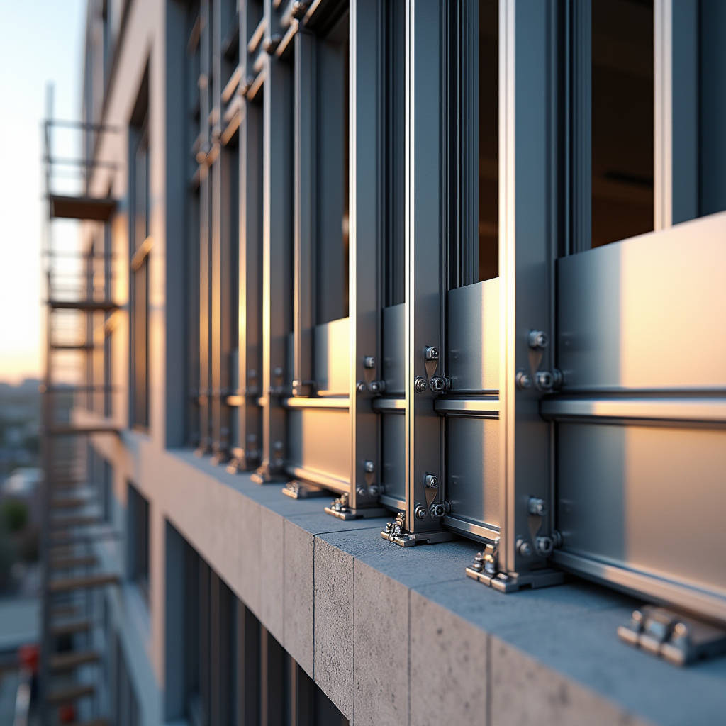
When a project team evaluates cladding options for a high-rise commercial tower, the conversation around Aluminium Facade systems often narrows to aesthetics and panel flatness. What gets overlooked until the submittal phase is the substructure, specifically the aluminium extrusion profiles that form the vertical and horizontal support grid behind every solid aluminium panel. A rainscreen facade is only as stable as its framing. The panels themselves, typically 2.5mm or 3.0mm solid aluminium sheets with PVDF coatings, carry inherent rigidity. But without a properly engineered rail and bracket assembly, even the flattest panel will telegraph irregularities across the building envelope within the first thermal cycle. This article examines the load path logic, alloy selection, thermal movement accommodation, and installation sequencing that determine whether an Aluminium Facade performs as designed or becomes a long-term liability for the contractor.
Why the Substructure Dictates Facade Longevity
Solid aluminium cladding panels are not structural elements. They span between attachment points and transfer wind loads, dead loads, and thermal stresses into the building's primary structure through a series of aluminium extrusions. The substructure does the heavy lifting. When a 3.0mm solid aluminium panel measuring 1,200mm by 3,000mm faces a design wind pressure of 2.4 kPa, the resulting load on each fixing point is substantial. The vertical T-profiles or hat sections, horizontal rails, and stainless steel brackets must be sized to handle these forces without exceeding deflection limits, typically L/360 for most commercial specifications under ASTM E330.
The choice of extrusion alloy matters. 6063-T6 aluminium offers a balance of extrudability and mechanical strength, with a tensile strength around 215 MPa. For projects in coastal environments or regions with higher wind loads, 6061-T6 extrusions provide roughly 30% greater tensile strength at 290 MPa, though at a higher cost per linear metre. The decision cascades through the entire system: stronger alloys allow wider mullion spacing, which reduces the total linear footage of extrusion required, partially offsetting the material premium. A detailed cost analysis at the shop drawing stage often reveals that the per-square-metre differential between 6063-T6 and 6061-T6 substructures narrows to 8-12% once labour and bracket counts are factored in.
Thermal Movement: The Silent Stressor
Aluminium expands and contracts at approximately 0.024mm per metre per degree Celsius. On a 40-metre-tall facade experiencing a 60°C temperature swing between a winter night and direct summer sun, the cumulative movement across the entire elevation can exceed 57mm. The substructure must absorb this movement without transferring stress to the panels or the building structure. Fixed points anchor the system at calculated locations, while sliding connections at every other bracket allow the extrusion to move freely.
The most common failure mode observed in forensic facade investigations involves installers rigidly fixing every bracket, eliminating the designed slip capacity. Within two to three seasonal cycles, panels begin to buckle, fastener heads pop, and the characteristic oil-canning distortion appears. For an Aluminium Facade with dark-coloured PVDF coatings, surface temperatures can reach 80°C in summer, making thermal movement calculations even more critical. The coefficient of thermal expansion for aluminium is roughly twice that of steel and three times that of concrete, which means the differential movement between the cladding system and the primary structure must be reconciled at every floor line.
Sliding vs. Fixed Connection Points
A well-designed substructure uses a grid of fixed and sliding connections. The fixed points, typically located at the centre of each panel or at predetermined structural nodes, transfer wind loads directly into the building. Sliding connections use slotted holes or proprietary sleeve systems that permit axial movement while maintaining lateral restraint. The slot length is calculated based on the distance from the nearest fixed point and the expected thermal range for the project location.
For a project in Dubai, where summer surface temperatures on aluminium panels can exceed 85°C and winter lows drop to 10°C, the slot length for a bracket 3 metres from the fixed point would be:
- Temperature range: 75°C
- Movement per metre: 0.024mm × 75 = 1.8mm
- Movement at 3m: 1.8mm × 3 = 5.4mm
- Required slot length with safety factor of 1.5: 8.1mm minimum
This level of calculation is standard practice for suppliers like Futeng®, whose engineering team reviews every shop drawing for thermal compatibility before fabrication begins. Skipping this step results in the kind of panel distortion that triggers costly remedial work and contractual disputes.
Bracket Systems and Load Transfer
The bracket is the interface between the aluminium substructure and the building's primary frame, whether that is structural steel, reinforced concrete, or CLT. Stainless steel grades 304 and 316 are standard for brackets, with 316 specified for marine or industrial environments where chloride exposure is a concern. The bracket design must address three load types simultaneously: dead load (self-weight of the cladding system), wind load (positive and negative pressure), and seismic load in applicable zones.
Adjustable brackets have become the industry norm for Aluminium Facade installations because they accommodate the dimensional tolerances of the primary structure, which can deviate by 15-25mm from design intent on concrete frames. A three-axis adjustable bracket allows the installer to set the exact plane of the finished facade regardless of substrate irregularities. The trade-off is cost: a three-axis stainless steel bracket assembly typically costs 40-60% more than a fixed bracket, but the reduction in shimming labour and the improvement in final facade flatness usually justify the premium on projects exceeding 5,000 square metres.
Rail Profiles and Span Tables
The vertical rails, often called mullions or T-profiles, are the primary load-bearing members in the substructure. Their depth, web thickness, and moment of inertia determine the maximum allowable span between bracket supports. A typical 6063-T6 T-profile measuring 60mm deep with a 3mm web thickness can span approximately 1,800mm between supports at a design wind load of 2.0 kPa while maintaining L/360 deflection. Increasing the profile depth to 80mm extends the allowable span to roughly 2,400mm under the same load conditions.
The table below provides a practical reference for engineers and facade contractors evaluating substructure options for solid aluminium cladding panels:
| Profile Depth (mm) | Alloy & Temper | Web Thickness (mm) | Max Span at 2.0 kPa (mm) | Max Span at 3.0 kPa (mm) | Approx. Weight (kg/m) |
|---|---|---|---|---|---|
| 50 | 6063-T6 | 2.5 | 1,400 | 1,100 | 1.35 |
| 60 | 6063-T6 | 3.0 | 1,800 | 1,450 | 1.80 |
| 80 | 6063-T6 | 3.0 | 2,400 | 1,950 | 2.30 |
| 80 | 6061-T6 | 3.5 | 2,700 | 2,200 | 2.75 |
| 100 | 6061-T6 | 4.0 | 3,200 | 2,600 | 3.60 |
These values assume simply supported beam conditions with uniform loading. Actual spans must be verified through project-specific structural calculations that account for building geometry, local wind codes, and the panel attachment method. The span tables published by the American Architectural Manufacturers Association (AAMA) provide additional guidance for engineers working in North American markets.
Panel-to-Substructure Attachment Methods
How a solid aluminium panel connects to the rail system affects both appearance and structural performance. The three dominant methods are exposed fastener, concealed clip, and cassette systems. Each has distinct implications for the substructure design.
Exposed Fastener Systems
Panels are screwed or riveted directly to the aluminium rails through pre-drilled holes in the panel face or returns. The fasteners remain visible, creating a rhythmic pattern across the facade. This method is the most economical, with installation rates of 15-20 square metres per installer per day. The substructure must provide continuous support along panel edges, typically requiring intermediate rails at 600mm to 900mm centres. Stainless steel fasteners with EPDM washers are essential to prevent galvanic corrosion and water ingress.
Concealed Clip Systems
Proprietary aluminium clips are riveted to the panel returns during fabrication. On site, the panels are hooked or clipped onto the horizontal rails without visible fasteners. This method demands tighter fabrication tolerances, typically ±1.5mm on panel dimensions, and the substructure must be installed to a plane tolerance of ±3mm over any 3-metre straight edge. The clip engagement depth, usually 12-15mm, must account for thermal movement so that panels do not disengage under negative wind pressure.
Cassette Systems
Folded aluminium cassettes with return edges on all four sides are hung from horizontal rails using integrated hooks or separate hanger brackets. Cassettes offer the cleanest aesthetic with shadow gaps between panels. The substructure for cassette systems typically uses horizontal rails at each floor level and intermediate horizontals at panel joints. Vertical alignment is maintained by the cassette geometry rather than continuous vertical rails, which can reduce the total aluminium in the substructure by 15-20% compared to a stick-built grid.
Corrosion Compatibility Between Dissimilar Metals
An Aluminium Facade substructure inevitably involves contact between aluminium extrusions and stainless steel fasteners, brackets, and anchors. In the presence of an electrolyte, typically rainwater carrying dissolved salts or pollutants, a galvanic cell forms. Aluminium is anodic to stainless steel, meaning the aluminium will corrode preferentially. The severity depends on the environmental exposure category defined in ISO 9223.
In C3 (medium) environments, such as urban areas with moderate pollution, the corrosion rate on unprotected aluminium in contact with stainless steel is generally manageable with proper isolation. In C5-M (marine) environments, the risk escalates significantly. The standard mitigation strategy includes:
- Isolating washers and bushings made from nylon or EPDM at every fastener penetration
- Applying a minimum 60-micron PVDF coating on all aluminium surfaces, including the hidden returns and stiffener ribs
- Specifying 316-grade stainless steel for all components within 5 kilometres of a coastline
- Ensuring drainage paths do not allow water to pond at bracket connections
The ISO 9223:2012 standard provides a systematic method for classifying atmospheric corrosivity, and reputable facade engineers reference it during the specification phase. Contractors who substitute 304 stainless for 316 in coastal projects to save cost are taking on liability that far exceeds the material savings.
Installation Sequencing and Quality Control
The best-engineered substructure will fail if installed out of sequence or without proper survey control. The installation workflow for a typical Aluminium Facade project follows a logic that must be enforced by the site manager:
- Primary survey and datum establishment: Laser scanning or total station survey of the structural frame establishes as-built dimensions. Benchmarks are transferred to each floor level.
- Bracket installation: Stainless steel brackets are fixed to the structure at calculated centres. Each bracket is surveyed for position and plane before tightening.
- Vertical rail installation: Aluminium mullions are hung from the brackets, with fixed and sliding connections installed per the shop drawings. Vertical alignment is checked with a plumb line or laser.
- Horizontal rail installation: Transoms are connected to the mullions, creating the grid. Diagonal measurements verify squareness across each bay.
- Panel hanging: Solid aluminium panels are installed from the bottom up or from a fixed corner outward, depending on the system. Each panel is checked for flushness with adjacent panels.
- Final adjustment and inspection: Any panel exceeding the specified flatness tolerance is adjusted at the bracket or clip level before the scaffold is dropped.
A common mistake is installing panels before the substructure grid has been fully surveyed and signed off. Once panels are on, access to the brackets for adjustment is lost. The cost of stripping panels to correct a misaligned rail can run to $45-60 per square metre in labour alone, not counting the risk of panel damage during removal and reinstallation.
Wind Load Considerations for Substructure Design
Wind loads govern the structural design of the substructure in most projects. The design wind pressure is calculated per the local building code, typically ASCE 7 in North America, EN 1991-1-4 in Europe, or AS/NZS 1170.2 in Australia and New Zealand. The key variables are basic wind speed, building height, exposure category, and the building's shape and surroundings.
Corner zones experience significantly higher suction pressures than the field of the wall. On a rectangular tower, the corner zone extending 1.5 metres from the building edge can see negative pressures 2.5 to 3 times higher than the positive pressure on the windward face. The substructure in these zones requires closer bracket spacing, deeper rail profiles, or both. A typical specification might call for bracket spacing of 1,200mm in the field and 800mm in corner zones, with rail profiles increased by one size increment.
The ASCE 7-22 standard includes updated wind speed maps and pressure coefficient tables that reflect recent research on cladding loads. Engineers designing substructures for projects in hurricane-prone regions should reference the latest edition and apply the appropriate importance factor for the building occupancy category.
Fire Performance of Aluminium Substructure Components
Solid aluminium panels and their aluminium substructure are non-combustible, classified as A1 under EN 13501-1 or as having a flame spread index of 0 under ASTM E84. This is a fundamental advantage over composite panels with polyethylene cores. However, aluminium loses approximately 50% of its strength at 200°C and essentially all structural capacity by 400°C. In a fire event, the substructure will soften and the panels may detach if the system is not designed with adequate fire stops and retention features.
Building codes in most jurisdictions require perimeter fire stopping at each floor level to prevent vertical fire spread through the cavity behind the rainscreen. Horizontal fire barriers, typically mineral wool with intumescent coatings, are installed between the back of the panel and the structural floor slab. The aluminium substructure must accommodate these barriers without compromising the thermal movement capability of the rails. This is achieved by designing the fire stop detail to allow the rail to slide through a sealed penetration rather than being rigidly clamped.
Cost Drivers in Substructure Engineering
The substructure typically accounts for 25-35% of the total installed cost of an Aluminium Facade system, excluding the panels themselves. Understanding what drives this cost helps project teams make informed decisions during value engineering:
- Bracket complexity: Three-axis adjustable brackets cost more than two-axis, which cost more than fixed. But the labour savings from faster installation often invert this hierarchy on larger projects.
- Rail spacing: Closer rail spacing means more linear metres of extrusion, more brackets, and more fasteners. Optimising the span-to-load ratio can reduce material quantities by 10-15%.
- Alloy selection: 6061-T6 costs approximately 18-22% more per kilogram than 6063-T6. The premium is justified only when the higher strength allows a meaningful reduction in profile size or bracket count.
- Surface treatment: Mill-finish extrusions are the cheapest but unsuitable for exposed applications. Anodised or powder-coated rails add cost but provide corrosion protection and a consistent appearance if visible behind open-joint panels.
- Site access: Scaffolding, mast climbers, or swing stages represent a significant portion of the installation cost. A substructure system that can be installed quickly from a single access position reduces the duration of access equipment rental.
On a recent 12,000-square-metre office tower project, switching from a fully fixed bracket system to a hybrid design with fixed points at every third floor and sliding connections elsewhere reduced the bracket count by 22% and shortened the installation programme by 11 working days, without any compromise in structural performance.
Specifying the Substructure: Key Contractual Considerations
For procurement managers and architects writing specifications, the substructure should be treated as an engineered system rather than a commodity. The specification should require the facade contractor to submit structural calculations stamped by a licensed engineer, along with shop drawings showing every bracket location, fixed and sliding connection, and fire stop detail. Performance requirements should reference specific standards:
- Structural performance: ASTM E330 for uniform static air pressure difference
- Water penetration: ASTM E331 for static water penetration resistance
- Air leakage: ASTM E283 for air leakage rate
- Thermal movement: Accommodation of movement per the calculated range without distress to panels or fasteners
The warranty period for the substructure should match or exceed the panel warranty, typically 20-25 years for PVDF-coated systems. The warranty should cover material defects, corrosion perforation, and structural failure of the extrusions and brackets under normal service conditions.
An Aluminium Facade represents a significant capital investment for any building. The panels are the visible face of that investment, but the substructure is what keeps them flat, secure, and performing for decades. Engineering the rail and bracket system with the same rigour applied to the panel specification is not optional. It is the difference between a facade that looks as good in year 15 as it did on day one, and one that requires intervention before the defects liability period expires. The calculations, material selections, and installation controls described here provide a framework for project teams to evaluate substructure proposals critically and to specify systems that match the performance expectations of the solid aluminium panels they support.