Aluminium Facade Panel Wind Load Resistance and Structural Engineering for Rainscreen Systems
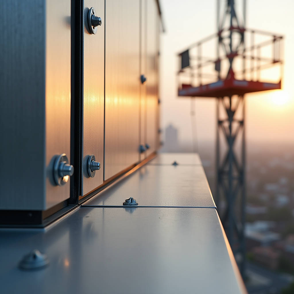
When a project specification lands on the desk of a facade engineer or procurement manager, the conversation around Aluminium Facade Panel systems rarely starts with aesthetics. It starts with numbers. Wind tunnel test reports, span tables, fastener shear capacities, and the nagging question of whether the 3.0mm thick panel specified on the drawings will actually survive a Category 4 cyclone without buckling or tearing at the anchor points. This article drills into the structural engineering side of solid aluminium rainscreen panels — specifically wind load resistance, deflection limits, and the connection design that separates a facade that stays put from one that becomes debris.
Why Wind Load Governs Aluminium Facade Panel Design
Wind is the single most aggressive load acting on a building envelope. Unlike dead loads or thermal movement, wind pressure is dynamic, reversing direction, peaking at building corners, and amplifying as height increases. For a solid Aluminium Facade Panel system, the structural chain is only as strong as its weakest link. That chain includes the panel itself, the fixing clips or brackets, the fasteners, and the aluminium subframe rails tied back to the primary structure.
ASCE 7-22 and EN 1991-1-4 both provide methodologies for calculating design wind pressure. The basic equation looks deceptively simple:
p = q × G × Cp − qi × GCpi
Where q is velocity pressure, G is the gust effect factor, Cp is the external pressure coefficient, and GCpi handles internal pressure. But the complexity hides in the coefficients. A 100-metre tower in Miami faces a different Cp profile than a low-rise warehouse in Manchester. Corner zones — typically defined as a distance equal to 20% of the building's least horizontal dimension — can see negative pressures (suction) 2.5 to 3 times higher than the centre of the wall. If the panel spec doesn't differentiate between corner and field zones, the installation is gambling.
Field Note: On a 2022 project in Singapore, we saw a contractor install identical 2.5mm solid aluminium panels across all zones. Within 18 months, corner-zone panels on the 22nd floor showed permanent deformation exceeding L/60. The root cause was simple: the same clip spacing used in the field zone was carried into corners where suction loads were 2.8× higher. Always request zone-specific shop drawings.
Panel Thickness and Span: The Deflection Limit Reality
Solid aluminium panels for exterior cladding typically come in 2.0mm, 2.5mm, and 3.0mm thicknesses. The choice isn't arbitrary — it's a direct function of span, load, and the deflection limit specified by the project. AAMA 508 and the older AAMA TIR-A9 provide guidance, but most project specifications default to L/60 for aluminium panels under wind load, where L is the span between supports in millimetres.
Here's what that means in practice. Take a 2.5mm thick Aluminium Facade Panel with a 600mm span between vertical support rails, facing a design wind pressure of 2.4 kPa. The deflection under uniform load can be estimated using plate theory. For a simply supported rectangular plate:
δmax = k × (p × a⁴) / (E × t³)
Where k is a coefficient depending on aspect ratio and boundary conditions, a is the shorter span, E is the elastic modulus of aluminium (≈ 69,000 MPa for 3003-H14 alloy), and t is the thickness. The cubic relationship with thickness is the critical insight — increasing from 2.0mm to 3.0mm doesn't give you 50% more stiffness; it gives you roughly 3.4× more. That's why a seemingly small thickness upgrade can eliminate the need for intermediate stiffeners, saving on fabrication labour and clip count.
| Panel Thickness | Span 600mm, 2.4 kPa | Span 800mm, 2.4 kPa | Span 600mm, 3.6 kPa |
|---|---|---|---|
| 2.0mm (3003-H14) | ~L/55 (marginal) | ~L/28 (fail) | ~L/36 (fail) |
| 2.5mm (3003-H14) | ~L/95 (pass) | ~L/48 (marginal) | ~L/62 (pass) |
| 3.0mm (3003-H14) | ~L/165 (pass) | ~L/83 (pass) | ~L/108 (pass) |
The table above uses simplified plate deflection estimates for square panels with four-edge support. Actual values depend on aspect ratio, rib stiffener patterns, and whether the panel edges are considered simply supported or partially fixed by the clip engagement. Always verify with physical mock-up testing per AAMA 501.1 when the calculated deflection exceeds L/90.
Clip and Fastener Design: The Overlooked Failure Point
Most post-storm facade failure investigations don't point to the panel tearing. They point to the clip pulling out of the subframe, the fastener shearing, or the aluminium rail itself buckling between tie-back anchors. The Aluminium Facade Panel might be perfectly intact — lying on the street three storeys below.
A typical rainscreen clip system involves an extruded aluminium clip riveted or screwed to the back of the panel, which then hooks or snaps onto a horizontal or vertical carrier rail. The load path is: wind pressure (or suction) → panel → rivets → clip → rail → rail-to-bracket fasteners → brackets → primary structure anchors.
Each connection point needs a documented allowable load. For a stainless steel blind rivet (say, 4.8mm diameter, A2/A4 grade) connecting clip to panel, the single-shear capacity in 2.5mm aluminium might be around 1.2–1.8 kN depending on edge distance and hole tolerance. If the design wind suction on a 1.2m × 0.6m panel is 3.0 kPa, the total load is 2.16 kN. With four clips per panel, each clip sees 0.54 kN — well within the rivet capacity. But if someone decides to save cost and use only three clips, the load per clip jumps to 0.72 kN, and now the safety factor shrinks.
Pro Tip: Don't just check the rivet shear. Check the bearing capacity of the aluminium panel around the rivet hole. In thin-gauge panels (2.0mm), bearing failure can occur before the rivet shears. The AISI and Eurocode 9 both provide bearing formulas. A quick rule of thumb: the bearing capacity of a 2.0mm 3003-H14 panel with a 4.8mm rivet at 20mm edge distance is roughly 0.9–1.1 kN. If your per-clip load exceeds this, increase the panel thickness or add more clips.
Thermal Movement: The Hidden Load Case
Wind isn't the only force trying to move the panels. Aluminium has a coefficient of thermal expansion of approximately 23.2 × 10⁻⁶ per °C. A 3-metre long Aluminium Facade Panel subjected to a 60°C temperature swing (from -10°C on a winter night to +50°C under direct summer sun) will expand by roughly 4.2mm. If the fixing system doesn't accommodate this movement, the panel will buckle — and buckling looks a lot like wind damage on a post-storm inspection report.
Fixed-point and sliding-point clip arrangements solve this. One clip (typically near the centre of the panel) is fixed rigidly, preventing translation. All other clips allow sliding in the plane of the panel, usually through slotted holes or a clip design that permits longitudinal movement. The slot length must exceed the calculated thermal movement plus a safety margin — typically 1.5× the calculated movement.
For a 3-metre panel with 4.2mm of movement, the sliding clips need at least 6.3mm of travel. If the slot is only 4mm, the panel will be restrained, and compressive stress builds up. The thermal stress can be estimated as:
σthermal = E × α × ΔT = 69,000 × 23.2×10⁻⁶ × 60 ≈ 96 MPa
That's approaching the yield strength of annealed 3003 aluminium (around 110–145 MPa depending on temper). Add wind stress on top, and you've got a problem that finite element analysis might catch — but only if someone remembers to include the thermal load case.
Alloy Selection: 3003, 5052, or Something Else?
Not all solid aluminium panels are metallurgically identical. The two most common alloys for facade applications are 3003-H14 and 5052-H32. The choice affects formability, corrosion resistance, and — critically for wind load design — yield strength.
3003-H14 is a general-purpose manganese-alloyed grade with a typical yield strength of 125–145 MPa. It forms well, welds easily, and costs less. 5052-H32 is a magnesium-alloyed grade with yield strength around 195–215 MPa — roughly 50% higher. For coastal projects where salt spray is a concern, 5052 also offers superior corrosion resistance. The trade-off is cost and slightly reduced formability for complex folded geometries.
From a wind load perspective, the higher yield strength of 5052 doesn't directly increase stiffness (E is nearly identical for both alloys), but it does increase the allowable stress before permanent deformation. If a project's wind load calculation shows that a 3003-H14 panel at 2.5mm thickness reaches 90% of yield at design load, switching to 5052-H32 drops that to about 60% — a much more comfortable margin without changing the panel gauge or span.
| Property | 3003-H14 | 5052-H32 |
|---|---|---|
| Yield Strength (MPa) | 125–145 | 195–215 |
| Tensile Strength (MPa) | 150–180 | 230–260 |
| Elastic Modulus (GPa) | 69 | 70 |
| Corrosion Resistance | Good (industrial) | Excellent (marine) |
| Formability | Excellent | Good |
| Relative Cost Index | 1.0 | 1.15–1.25 |
Subframe and Bracket Design: Connecting to the Building
The aluminium subframe — typically vertical T-profiles or hat channels — transfers panel loads to the structural wall through adjustable brackets. The subframe itself is a continuous beam subjected to point loads from each panel clip. If the bracket spacing is too wide, the subframe deflects between brackets, and the panel deflection adds to it. Total system deflection is the sum of panel deflection plus subframe deflection, and the L/60 limit applies to the total.
A common subframe rail is a 60mm × 40mm × 3mm aluminium box section or a 50mm deep hat channel in 2.5mm gauge. With brackets at 1200mm centres and clip loads of 0.5 kN at 600mm intervals, the subframe deflection between brackets might be in the range of 1.0–1.5mm. That's L/800 to L/1200 — negligible on its own, but it adds to the panel's L/95 deflection. Combined, you might drop from L/95 to around L/78, still passing but with less headroom than the panel-only calculation suggests.
Bracket thermal isolation is another detail that gets missed. If the aluminium subframe is directly connected to a steel primary structure without a thermal break, galvanic corrosion becomes a risk. A 0.5mm thick PVC or EPDM isolator pad between the bracket and the steel embed is cheap insurance. The AAMA 609.1 standard covers the requirements for these thermal breaks in wall assemblies.
Testing and Verification: Beyond the Spreadsheet
Calculations get you to the shop drawing stage. Testing proves the system works. For Aluminium Facade Panel systems on buildings over 18 metres or in high-wind zones, a full-scale mock-up test per ASTM E330 (uniform static air pressure difference) is standard practice. The test applies positive and negative pressure in increments — 50%, 75%, 100%, and 150% of design load — while measuring deflection at multiple points.
The pass/fail criteria under ASTM E330 are straightforward: at 100% of design load, the maximum deflection must not exceed L/60 for the panel and subframe combined. At 150%, the system must not experience permanent damage or failure of any component. If a clip tears out at 135%, the design fails — even if the 100% deflection was within limits.
Dynamic wind testing per ASTM E1592 adds another layer, cycling the pressure thousands of times to simulate fatigue. Aluminium panels are generally good in fatigue, but the connections — rivets, screws, clip engagement — are where fatigue cracks initiate. A well-designed system should survive 5,000 cycles at 100% of design load without loosening or cracking.
Specification Language: What to Write in the Tender
For procurement managers and spec writers, vague language invites value-engineering that can gut the wind resistance of the system. A specification that says "aluminium cladding panels to engineer's approval" is a liability. Here's what a robust performance specification should include for wind load:
- Design wind pressure: State the zone-specific pressures (corner, edge, field) in kPa, referencing the project's wind tunnel report or the local building code.
- Deflection limit: L/60 under design wind load, measured as total system deflection including panel, clip, and subframe contributions.
- Panel alloy and temper: Specify 3003-H14 or 5052-H32. If the project is within 5km of a marine coastline, 5052-H32 or PVDF-coated 3003 with chromate pretreatment should be mandatory.
- Clip material: Extruded aluminium 6063-T5 or T6, with stainless steel fasteners (A2 or A4 grade). No galvanised steel clips in contact with aluminium panels.
- Testing requirements: ASTM E330 static pressure test at 150% of design load, ASTM E1592 cyclic test, and AAMA 501.1 dynamic water penetration test on a full-scale mock-up.
- Thermal movement accommodation: Sliding clips with minimum slot length equal to 1.5× calculated thermal movement. Fixed point at panel centre.
Suppliers like Futeng® who specialise in solid aluminium facade systems can provide technical data sheets with pre-calculated span tables for their standard panel and clip configurations. This doesn't replace project-specific engineering, but it provides a solid starting point for preliminary design and budgeting.
Coastal and Extreme Climate Considerations
Wind loads in coastal zones come with a corrosive partner: salt spray. The combination of high wind suction and chloride-induced pitting can accelerate failure at fastener holes and clip contact points. For projects within 500 metres of breaking surf, the ISO 9223 corrosivity classification typically falls into C4 or C5 — high to very high. At these levels, standard 3003 alloy with a basic polyester powder coat won't cut it.
The minimum specification for a marine-environment Aluminium Facade Panel should include: 5052-H32 alloy, chromate conversion coating pretreatment per ASTM B449, and a PVDF (polyvinylidene fluoride) coil or spray coating with a minimum 70% Kynar 500® resin content at 25–35 microns dry film thickness. All fasteners should be A4 (316) stainless steel, and the aluminium subframe should be anodised to AA25 (25 microns) minimum.
There's also a practical installation consideration: in coastal zones, the wind often carries fine sand and salt particles. Over years, this can erode the coating at panel edges and around reveals. Specifying a 3-coat PVDF system (primer + colour coat + clear topcoat) with a total DFT of 40–45 microns provides measurably better edge protection than a 2-coat system at 25 microns.
Balancing Cost and Safety: The Engineering Judgment
Every project walks a line between over-engineering (which kills the budget) and under-engineering (which kills the warranty — or worse). The skill is in knowing where to spend and where to save. Based on two decades of facade engineering experience, here's where the money should go:
- Spend on clips and fasteners. The difference between a stamped aluminium clip and a machined 6063-T6 extrusion with a proper sliding mechanism might be $0.80 per clip. On a 10,000-panel project, that's $32,000. A single panel detachment incident costs far more in investigation, replacement, and reputation damage.
- Don't over-spend on panel thickness if the subframe is the limiting factor. If the subframe deflects L/70 at 2.5mm panel gauge, upgrading to 3.0mm panels won't improve the total system deflection by much. Fix the subframe first.
- Invest in mock-up testing. A $15,000–25,000 mock-up test can reveal problems that would cost hundreds of thousands to fix post-installation. The mock-up should include at least two full bays, one corner zone, and all typical interface details with windows, louvers, and parapets.
The Centre for Window and Cladding Technology (CWCT) in the UK publishes excellent guidance on rainscreen design and testing that applies globally. Their technical notes on wind load testing and bracket design are referenced in specifications across Europe, the Middle East, and Asia.
Final Thoughts on Wind-Resistant Aluminium Facade Panel Design
Wind resistance in solid aluminium facade systems isn't a single number on a datasheet. It's a chain of design decisions — alloy grade, panel thickness, clip type, fastener specification, subframe stiffness, bracket spacing, thermal movement accommodation, and corrosion protection. Each link matters. The engineer who only checks panel deflection and ignores clip pull-out capacity is designing a system that looks good on the drawing board and fails in the field.
For procurement teams, the takeaway is to demand more than a price per square metre. Request span tables, clip load test reports, and corrosion certifications. For architects, the takeaway is to specify performance criteria rather than prescriptive dimensions — let the facade engineer determine the panel thickness and clip spacing based on the wind loads, not a generic table from a catalogue. A correctly engineered Aluminium Facade Panel system will handle design wind loads with controlled deflection, accommodate thermal movement without buckling, and resist corrosion for decades. Getting there requires attention to detail at every link in the structural chain.