Aluminium Facade Substructure Design and Thermal Expansion Engineering for Solid Cladding Panels
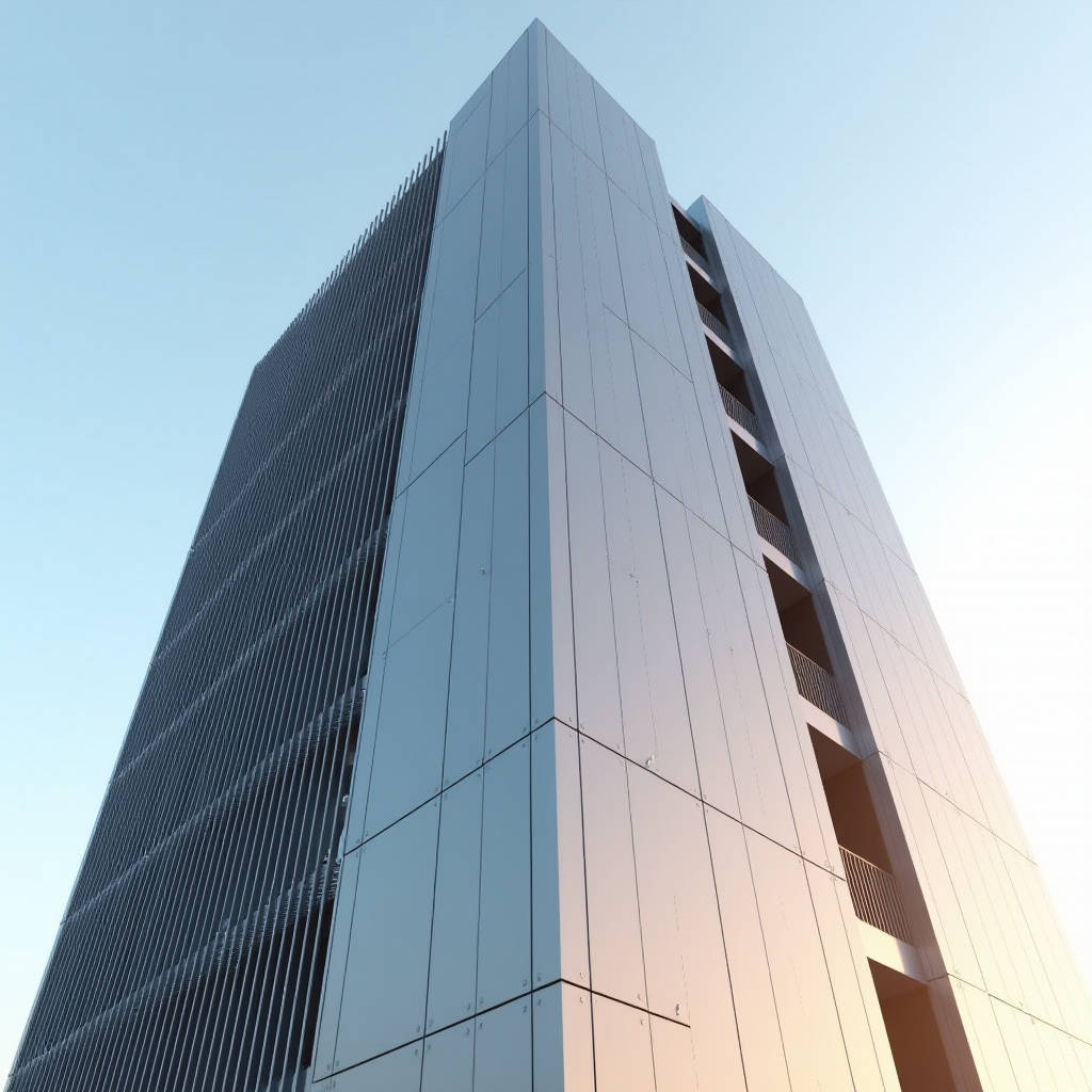
When specifying an Aluminium Facade for a high-rise commercial or institutional building, the performance of the rainscreen system hinges on two often underestimated factors: the structural integrity of the aluminium substructure and the precision of the panel attachment system. Many project teams focus solely on the visible panel finish, yet field failures—ranging from oil-canning to thermal buckling—frequently trace back to inadequate substructure design or improper allowance for thermal movement. This article examines the engineering principles behind aluminium facade substructures, the critical role of thermal expansion gaps, and the practical installation tolerances that separate a durable building envelope from a costly remediation project. Drawing on international standards and real-world contracting experience, we provide B2B specifiers and facade contractors with actionable data for designing and installing solid aluminium cladding panels that perform reliably across diverse climates.
Why the Substructure Determines Facade Longevity
The visible solid aluminium panels of a rainscreen facade are only as good as the supporting framework behind them. The substructure—typically extruded aluminium brackets, vertical rails, and horizontal transoms—transfers wind loads, dead loads, and thermal stresses from the panel face to the building's primary structure. A poorly designed substructure leads to panel misalignment, fastener fatigue, and compromised weather sealing.
For solid aluminium panels with thicknesses of 2.0 mm, 2.5 mm, or 3.0 mm, the substructure spacing must be calculated based on the panel's flexural rigidity. The modulus of elasticity of aluminium (approximately 69 GPa) is one-third that of steel, meaning deflection under wind load must be checked carefully. Most international codes, including the AAMA 501.1 standard for dynamic water penetration testing, require that the maximum deflection of any facade component not exceed L/240 of the span. For a typical 1200 mm wide panel, this translates to a maximum allowable deflection of 5 mm under design wind pressure.
Field Note: On a recent 40-storey tower in Southeast Asia, the contractor used 1.5 mm thick brackets instead of the specified 3.0 mm. Under typhoon-level wind loads, the brackets deformed, causing 15 mm of panel displacement. The entire lower 20 floors had to be re-clad at a cost exceeding USD 1.2 million. Never compromise on bracket gauge.
Thermal Expansion: The Hidden Driver of Joint Design
Aluminium has a coefficient of linear thermal expansion of approximately 23.2 × 10⁻⁶ /°C. For a 3000 mm long solid aluminium panel exposed to a temperature differential of 70°C (from a winter night of -10°C to a sun-baked surface of 60°C), the linear expansion calculates to:
ΔL = 23.2 × 10⁻⁶ × 3000 × 70 = 4.87 mm
This nearly 5 mm movement must be accommodated at every joint. If expansion gaps are undersized or blocked by debris, the panels will buckle, causing permanent distortion known as oil-canning. The table below summarizes recommended minimum expansion gaps based on panel length and expected temperature range, derived from data in the Aluminum Association's "Aluminum Design Manual."
| Panel Length (mm) | Temperature Range (°C) | Calculated Expansion (mm) | Recommended Minimum Gap (mm) |
|---|---|---|---|
| 1500 | 50 | 1.74 | 5 |
| 3000 | 50 | 3.48 | 8 |
| 3000 | 70 | 4.87 | 10 |
| 4500 | 70 | 7.31 | 14 |
| 6000 | 80 | 11.14 | 18 |
These gaps are not merely aesthetic joints. They must be designed with a compatible backer rod and sealant that can accommodate the full range of movement without losing adhesion. Silicone sealants with a movement capability of ±50% are standard for aluminium facade joints, in accordance with ASTM C920.
Attachment Systems: Structural vs. Non-Structural Fixings
Solid aluminium cladding panels are typically attached using one of three methods: concealed clip systems, exposed screw-fixed systems, or cassette-style hook-on systems. Each has distinct structural characteristics and cost implications.
Concealed Clip Systems
These systems use aluminium clips that engage with the panel's folded edges. The clip is fastened to the substructure rail, allowing the panel to be installed without visible fasteners. This method provides excellent thermal movement accommodation because the clip allows the panel to slide relative to the rail. However, the clip material and gauge must be matched to the expected wind load. A 2.0 mm thick 6063-T5 aluminium clip can typically resist a pull-out load of 800 N to 1200 N, depending on the design. For high-wind zones, stainless steel clips or thicker aluminium clips are recommended.
Exposed Screw-Fixed Systems
In this method, self-tapping stainless steel screws pass through the panel face into the substructure. While faster to install and lower in material cost, exposed fixings create thermal bridges and potential leak paths. Each screw head must be sealed with a gasket or cap. The thermal expansion of the panel must be absorbed by oversized holes in the panel—typically 2 mm larger than the screw diameter. This method is best suited for low-rise applications where wind loads are below 1.5 kPa and aesthetic requirements are less stringent.
Cassette Hook-On Systems
Cassette panels have a folded tray profile with a hooked top edge that engages with a receiving rail on the substructure. The bottom edge is secured with a locking clip or screw. This system combines the clean appearance of concealed fixings with the ease of individual panel removal for maintenance. The hook engagement depth must be at least 12 mm to ensure secure load transfer, as specified in the EOTA European Assessment Document for rainscreen systems.
Corrosion Protection and Galvanic Compatibility
When aluminium substructures interface with stainless steel fasteners or carbon steel brackets, galvanic corrosion becomes a genuine risk. The electrolyte (rainwater, condensation) completes the circuit, and the less noble metal (aluminium) corrodes preferentially. To mitigate this:
- Use stainless steel grade 316 fasteners for coastal or industrial environments. Grade 304 is acceptable for inland projects.
- Apply a nylon or EPDM isolator between aluminium components and any dissimilar metal.
- Ensure that the substructure's surface treatment (anodizing or powder coating) is intact at all contact points.
- Do not use copper or brass components anywhere in the aluminium facade assembly.
The AAMA 2605 specification for high-performance organic coatings on aluminium extrusions provides a benchmark for corrosion resistance. A properly applied 70% PVDF (Kynar 500) coating on the substructure—not just the visible panels—adds a significant layer of protection against atmospheric corrosion.
Installation Tolerances: What the Field Actually Requires
The gap between design drawings and site conditions is where most facade problems originate. Concrete slabs and steel frames have construction tolerances far larger than what an aluminium facade system can absorb. The following installation tolerances are recommended for solid aluminium cladding systems, based on the AAMA 503 standard for field testing of curtain walls:
- Substructure vertical alignment: ±3 mm over 3 m length
- Substructure horizontal alignment: ±2 mm over 3 m length
- Panel-to-panel gap variation: ±1.5 mm
- Panel flatness deviation: ±2 mm over 2 m straightedge
- Fastener torque: Within ±10% of specified value
If the building's primary structure deviates beyond these limits, shimming or custom bracket fabrication is required before panel installation begins. Never attempt to "pull in" misaligned panels by over-tightening fasteners—this induces stress that leads to oil-canning and potential fatigue cracking over time.
Pro Tip: Before any panel is installed, conduct a full laser survey of the building's facade grid. Compare the survey data to the shop drawings. If deviations exceed 5 mm at any point, stop work and resolve the substructure alignment first. This single step can prevent 80% of field-fit problems.
Wind Load Design and Panel Thickness Selection
Selecting the correct panel thickness is a function of wind load, panel size, and allowable deflection. For a 1200 mm × 2400 mm panel subjected to a design wind pressure of 2.5 kPa (typical for 30-40 storey buildings in moderate wind zones), the required panel thickness can be estimated using the following approach based on the Aluminum Association's "Specification for Aluminum Structures":
The required section modulus per unit width is calculated, and from that, the minimum thickness is derived. For a simply supported plate with four edges fixed, a 2.5 mm thick solid aluminium panel (AA 3003 or 5005 series, H14 temper) will typically satisfy deflection limits for spans up to 1200 mm in both directions. For larger panels or higher wind loads, 3.0 mm thickness is recommended. The table below provides a quick reference:
| Design Wind Pressure (kPa) | Max Panel Width (mm) | Recommended Thickness (mm) | Max Deflection (mm) |
|---|---|---|---|
| 1.5 | 1200 | 2.0 | 5.0 |
| 2.5 | 1200 | 2.5 | 5.0 |
| 3.5 | 1200 | 3.0 | 5.0 |
| 2.5 | 1500 | 3.0 | 6.25 |
| 3.5 | 1500 | 3.0 (with intermediate support) | 6.25 |
These calculations assume a panel edge condition of continuous support on all four sides. If the design uses a point-fixed or frameless system, the stress distribution changes significantly, and finite element analysis (FEA) is strongly recommended. Suppliers such as Futeng® offer engineering support for panel thickness optimization based on project-specific wind tunnel data, which can reduce material costs without compromising safety.
Quality Control in Panel Fabrication
The dimensional accuracy of solid aluminium panels directly affects installation speed and final appearance. Key quality control parameters that should be specified in the procurement contract include:
- Panel flatness: Maximum deviation of 1.5 mm per 1000 mm when measured on a granite surface plate, per ASTM B209.
- Edge straightness: Maximum deviation of 1 mm per 2000 mm length.
- Corner squareness: Diagonal difference not exceeding 2 mm for panels up to 3000 mm.
- Coating thickness: For PVDF (Kynar 500) coatings, minimum total dry film thickness of 25 microns per AAMA 2605. For polyester powder coatings, minimum 60 microns per AAMA 2604.
- Color consistency: Delta E (ΔE) of ≤ 1.0 when measured with a spectrophotometer under D65 illuminant, per ASTM D2244.
These specifications should be written into the tender documents and verified through third-party inspection at the factory before shipment. For international projects, particularly those involving sea freight, the packing standard is equally critical. Each panel should be separated by interleaving paper or foam, stacked in wooden crates with internal bracing, and wrapped in shrink film with desiccant packs. The crates must be designed to prevent panel flexing during lifting and transport.
Logistics Considerations for Global Projects
When sourcing solid aluminium cladding panels from overseas manufacturers, the Incoterms and packing specifications directly affect project timelines and budget. The following points are frequently overlooked:
- FOB vs. CIF: Under FOB terms, the buyer assumes risk once the cargo is loaded. For high-value facade panels, CIF with marine insurance is strongly recommended.
- Moisture protection: Wooden crates must be heat-treated and marked with IPPC certification. Vapor barrier liners and silica gel desiccant packs should be specified in the packing clause.
- Container loading: Panels should be loaded vertically or at a slight angle, never flat-stacked, to prevent bowing. Each crate should be secured with polyester strapping, not steel bands, to avoid edge damage.
- Lead time: For PVDF-coated panels with custom colors, allow 4-6 weeks from approved shop drawings to factory completion. Add 3-5 weeks for sea freight depending on the route.
Experienced suppliers like Futeng® provide detailed packing plans and loading photos for each shipment, which can be used to verify compliance with the contract specifications before the cargo leaves the factory.
Conclusion
A durable and visually consistent Aluminium Facade system is not achieved by panel selection alone. The substructure design, thermal expansion accommodation, attachment method, corrosion protection, and field installation tolerances must all be engineered as an integrated system. By specifying solid aluminium panels with the correct thickness for the wind load, designing substructures with adequate stiffness, and enforcing strict quality control and packing standards, facade contractors and building owners can avoid the most common failure modes. Reference the AAMA 501, ASTM B209, and ISO 9001 standards in your project specifications, and verify compliance through independent testing and factory inspection. The upfront investment in engineering rigor pays dividends in building performance and maintenance cost savings over the structure's service life.