How Wind Load and Panel Span Determine Aluminum Cladding Thickness on Solid Facades
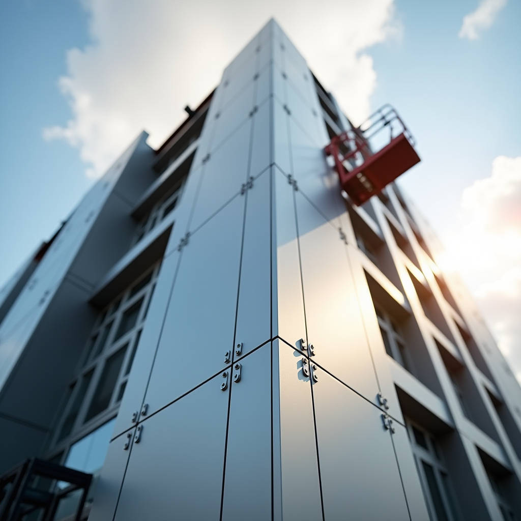
When a facade consultant specifies solid aluminum cladding on a high-rise in Dubai, the first question from the cost estimator is rarely about alloy grade or PVDF chemistry. It is about thickness. More precisely, it is about whether 2.5 mm will pass the wind load review or whether the project can absorb the cost delta of stepping up to 3.0 mm across 8,000 square meters. The answer is never a single number. It lives inside a matrix of panel dimensions, fixing methods, stiffener layouts, and the specific wind zone where the building stands. The term aluminum cladding thickness gets thrown around in tender documents as if it were a standalone specification. In practice, thickness is a dependent variable. Engineers who treat it as an independent input tend to produce facades that either leak at the joints or blow through the project budget on unnecessary metal mass.
Why Wind Load Rewrites the Thickness Conversation
Wind pressure does not distribute evenly across a facade. Corner zones on tall buildings experience suction forces that can be two to three times higher than the field area. A 2.5 mm solid aluminum panel that performs perfectly on the broad face of a mid-rise office block may buckle under the negative pressure at the parapet edge of a 40-story tower. The calculation chain starts with the local building code. ASCE 7 in the United States, EN 1991-1-4 in Europe, and AS/NZS 1170.2 in Australia all provide methods for deriving design wind pressures based on building height, exposure category, and topographic factors. From there, the facade engineer maps those pressures onto the panel grid. A 1,200 mm × 3,000 mm panel spanning between two horizontal girts sees a different bending moment than a 600 mm × 600 mm cassette supported on all four edges. The aluminum cladding thickness that satisfies deflection limits under the first scenario might be 3.0 mm. Under the second, 2.0 mm could clear the same criteria with margin to spare.
What trips up many procurement teams is the assumption that a thicker panel is always safer. In aluminum solid sheet cladding, thickness adds stiffness, but stiffness also comes from geometry. A 2.5 mm panel with 25 mm folded returns on all four edges and a properly bonded aluminum stiffener at mid-span can outperform a flat 3.0 mm sheet with no returns. The folded edge acts as a flange, dramatically increasing the section modulus. This is why experienced fabricators push back when a specification simply says "3.0 mm minimum thickness" without referencing panel size, stiffener layout, or support spacing.
Field Note: On a recent mixed-use project in Jeddah, the original specification called for 3.0 mm solid aluminum across all facade zones. After wind tunnel testing, the corner panels required 3.0 mm with two horizontal stiffeners, while the field panels passed at 2.5 mm with a single stiffener. The material cost saving on the field area alone covered the entire wind tunnel study fee. Always request the zone-by-zone pressure map before locking in your panel schedule.
Deflection Limits and the Real Stiffness Threshold
Most international aluminum curtain wall standards set a deflection limit of L/175 to L/200 under design wind load, where L is the span between supports. For a 1,500 mm span, that means allowable deflection falls between 7.5 mm and 8.6 mm. A 2.0 mm solid aluminum panel spanning 1,500 mm without stiffeners will typically exceed this limit at moderate wind pressures. Bump the thickness to 2.5 mm and the deflection drops by roughly 40% because bending stiffness scales with the cube of thickness. Going to 3.0 mm buys another 30% reduction. But those numbers assume a flat plate. Add a folded return or a bonded stiffener, and the effective stiffness jumps by an order of magnitude.
The alloy selection matters here. Aluminum alloy 5052 H32, widely used in solid cladding, offers a tensile strength around 230 MPa and yield strength near 195 MPa. Alloy 3003 H14, common in less demanding applications, yields closer to 145 MPa. If a specification calls for 3003, the same span and wind load might demand a 3.0 mm panel where 5052 could work at 2.5 mm. The temper designation is not decorative. H32 means strain-hardened and stabilized. H14 means strain-hardened only. The difference shows up in long-term creep behavior under sustained load, particularly on dark-colored panels that reach high surface temperatures in direct sun.
Temperature is the silent variable in the aluminum cladding thickness discussion. Aluminum expands at roughly 0.024 mm per meter per degree Celsius. A 3,000 mm panel on a black PVDF finish in Riyadh can swing from 15°C at night to 80°C in afternoon sun. That is a 65°C delta, producing 4.7 mm of thermal movement. A thicker panel does not expand less. It expands with more force. The joint design must accommodate this movement regardless of thickness. But thicker panels, being stiffer, transmit more stress into the fixings and the substructure. If the fixing system was designed for 2.5 mm panels and the project upgrades to 3.0 mm late in the game, the thermal stress on the anchor points increases. This is rarely checked and occasionally causes fastener fatigue in cyclic conditions.
Fabrication Geometry and the Minimum Practical Gauge
Solid aluminum panels are rarely flat sheets. They get routed, folded, welded, and perforated. Each fabrication step has a minimum thickness requirement dictated by the tooling and the desired edge quality. Routing a V-groove for a sharp folded corner on a 2.0 mm panel leaves a residual web thickness of perhaps 0.5 mm to 0.8 mm. That is enough to hold the corner but not enough to survive rough handling on site. At 2.5 mm, the residual web can be 0.8 mm to 1.0 mm, which is far more forgiving. At 3.0 mm, fabricators can confidently leave 1.0 mm to 1.2 mm and still produce a crisp corner. This is why many fabricators quietly prefer 2.5 mm as the practical minimum for panels with folded returns and 3.0 mm for panels with deep draws or complex geometries.
Perforated panels introduce another constraint. When a panel is punched with holes for acoustic backing or decorative screening, the open area reduces the effective stiffness. A 2.5 mm panel with 30% open area behaves more like a 2.0 mm solid panel in bending. The specifier must either increase the base thickness or reduce the span between supports. The AAMA 508 and 509 standards provide test methods for determining the structural performance of curtain wall panels but do not directly prescribe thickness for perforated conditions. That falls to the engineer's judgment and, increasingly, to finite element analysis performed by the fabricator.
Coating Systems and the Thickness They Add
PVDF coatings based on Kynar 500 or Hylar 5000 resin systems are the industry standard for exterior solid aluminum cladding. The dry film thickness of a three-coat PVDF system typically runs 30 to 35 microns, with a primer coat of 5 to 8 microns, a color coat of 15 to 20 microns, and a clear topcoat of 10 to 12 microns. This is negligible relative to the aluminum substrate thickness. But the coating specification interacts with thickness in one critical way: the pretreatment and baking cycle. Panels pass through a chromate conversion coating line, then a spray booth, then a curing oven that reaches 230°C to 250°C. Thinner panels heat up faster and can distort if the oven profile is not adjusted. A 2.0 mm panel is more prone to thermal distortion during curing than a 3.0 mm panel. This is a production reality that architects never see but that fabricators manage daily.
For projects within 5 km of a marine coastline, the coating specification tightens. AAMA 2605 requires superior color retention and chalk resistance, and the pretreatment must meet marine-grade standards for corrosion resistance. The aluminum substrate thickness does not change. But the expectation of service life does. A 2.5 mm panel with a properly applied PVDF coating can serve 30 years in a coastal environment if the edges are sealed and the fixings are stainless steel. Cut corners on edge sealing, and the panel thickness becomes irrelevant because corrosion will start at the cut edges regardless of whether the sheet is 2.0 mm or 3.0 mm thick.
Pro Tip: When specifying solid aluminum cladding for coastal projects, include a requirement for edge sealant application on all cut and routed edges after fabrication. The edge sealant should be a two-part epoxy or a high-solids polyurethane compatible with the PVDF topcoat. This is often overlooked in tender documents and becomes a costly variation order later.
Support Spacing and the Economics of Substructure
The substructure that supports solid aluminum panels is typically aluminum extruded profiles, galvanized steel channels, or a unitized stick system. The spacing of horizontal girts and vertical mullions directly determines the span that each panel must clear. Tighten the support spacing, and you can use thinner panels. Widen it, and you need thicker panels or more stiffeners. The economic trade-off is not obvious. Aluminum extrusion costs roughly $4 to $6 per kilogram in volume. A 2.5 mm panel weighs about 6.75 kg per square meter. A 3.0 mm panel weighs 8.1 kg per square meter. The material cost difference is roughly $3 to $5 per square meter at current aluminum pricing. But if stepping from 3.0 mm to 2.5 mm requires adding an extra row of horizontal girts at every floor level, the additional substructure cost can easily exceed $15 per square meter. The optimal solution usually lands on the thicker panel with wider support spacing.
This is where the aluminum cladding thickness decision becomes a system-level optimization rather than a material selection exercise. The best facade contractors run the numbers both ways during the value engineering phase. They compare total installed cost of (2.5 mm + closer support spacing) versus (3.0 mm + wider spacing) and present the delta to the client. The answer changes project to project. There is no universal rule.
| Panel Thickness | Typical Max Span (mm) | Weight (kg/m²) | Relative Material Cost | Best Suited For |
|---|---|---|---|---|
| 2.0 mm | 600 – 800 | 5.4 | Low | Small modules, soffits, interior cladding |
| 2.5 mm | 800 – 1,200 | 6.75 | Medium | Mid-size facade panels, moderate wind zones |
| 3.0 mm | 1,200 – 1,600 | 8.1 | High | Large panels, high wind zones, deep forming |
| 4.0 mm | 1,600 – 2,000 | 10.8 | Premium | Column covers, feature elements, blast zones |
The span values in the table assume aluminum alloy 5052 H32, folded returns on all edges, and a deflection limit of L/175. Projects with stricter deflection criteria or higher design wind pressures will need to reduce these spans or increase the thickness. The table is a starting point for budgeting, not a substitute for engineering analysis.
International Shipping, Handling, and the Flatness Problem
Solid aluminum panels travel from factory to site in containers, on flatbed trucks, and sometimes on open-deck vessels. A 2.0 mm panel that leaves the factory perfectly flat can arrive on site with a visible oil-canning effect simply from being stacked and vibrated during transit. Thicker panels resist handling damage better. But even 3.0 mm panels can develop waves if they are not packed correctly. The industry standard is to ship panels vertically in purpose-built steel stillages with foam separators between each panel. Horizontal stacking invites deflection under self-weight, especially for panels larger than 2 square meters.
For international projects, the logistics chain adds another layer to the thickness decision. Panels specified at 2.5 mm may arrive with minor edge dents that require on-site touch-up. Panels at 3.0 mm are more robust but heavier, increasing freight costs. The weight difference between 2.5 mm and 3.0 mm across a 5,000-square-meter project is roughly 6.75 metric tons. That translates to additional container loads or higher LCL charges. The procurement team must weigh the reduced site damage claims against the increased freight cost. In our experience at Futeng®, we have seen projects where the freight savings from sticking with 2.5 mm panels were entirely consumed by the cost of replacing panels damaged in transit. The project team ended up air-freighting replacement panels at emergency rates, which wiped out any initial savings.
Code Requirements and Fire Performance
Solid aluminum cladding is non-combustible. Aluminum alloy 5052 and 3003 both meet the requirements of ASTM E136 for non-combustibility and achieve an A1 rating under EN 13501-1. This is a fundamental advantage over composite panels with polyethylene cores, which have been the subject of well-publicized fire incidents and regulatory crackdowns globally. The aluminum cladding thickness does not affect the non-combustible classification. A 2.0 mm solid aluminum panel and a 3.0 mm solid aluminum panel are both A1. But thickness does affect the panel's behavior in a fire. Thinner panels lose structural integrity faster when exposed to flame. They soften and deflect sooner, which can create gaps in the facade that allow fire to spread vertically. Some jurisdictions, particularly in the Middle East and Australia, now require minimum 3.0 mm solid aluminum for certain high-risk building types as part of their post-Grenfell regulatory reforms.
The ISO 13785 series provides test methods for facade fire propagation. While the standard does not prescribe a minimum thickness, the test results consistently show that thicker solid aluminum panels maintain their integrity longer under radiant heat exposure. This is a secondary benefit that rarely makes it into the specification but is worth knowing when working on projects where fire engineering is under intense scrutiny.
Making the Call: A Decision Framework
The right aluminum cladding thickness for a project emerges from answering five questions in sequence. First, what are the design wind pressures by zone, and what deflection limit applies? Second, what is the panel grid and support spacing? Third, what fabrication processes are required: routing, folding, perforating, welding? Fourth, what is the project location relative to the coast, and what coating specification applies? Fifth, what is the logistics chain, and what level of handling robustness is needed?
Answer those five questions, and the thickness range narrows to a specific number for each facade zone. Skip any one of them, and the specification becomes a guess. The industry has moved past the era when "3.0 mm" was the default answer for everything. Today's best facade engineers treat thickness as a performance variable, not a fixed specification. They specify the performance requirements and let the fabricator propose the thickness that meets them, backed by calculations and test data. This approach produces facades that are safer, lighter, and more economical. It also shifts the conversation from "how thick" to "how stiff," which is where it should have been all along.
For procurement managers and quantity surveyors, the practical takeaway is straightforward. Do not bid a project based solely on a thickness number in a specification. Request the structural calculations. Understand the support spacing and the wind loads. Compare the total system cost, not just the panel material cost. A supplier quoting 2.5 mm with a comprehensive stiffener layout may deliver better value than one quoting 3.0 mm with no stiffeners and wider support spacing. The number on the spec sheet is the beginning of the conversation, not the end.
Standards referenced in this article include ASTM E136 for non-combustibility testing, AAMA 2605 for high-performance organic coatings on aluminum, and ISO 13785 for facade fire propagation. These documents form the technical backbone of any defensible aluminum cladding thickness specification.