How Custom Aluminum Panel Dimensions Affect Container Freight and Site Installation
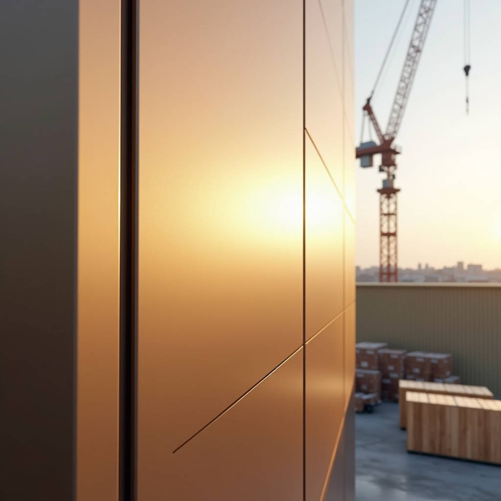
Getting the dimensions wrong on a custom aluminum panel order is not a minor paperwork error. It is the kind of mistake that stops a tower crane from unloading crates, forces a crew to stand idle on a swing stage, and triggers a chain of emails between the GC, the architect, and the fabricator that nobody wants to read. For solid aluminum cladding panels — 2.0 mm, 2.5 mm, or 3.0 mm thick, PVDF-coated, fabricated to a facade-specific cutting list — the dimensional data you submit at the purchase order stage dictates everything: freight class, container utilization, bracket spacing, and whether the panels actually fit the substructure on site. This article focuses on the dimensioning logic that separates a smooth installation from a logistical headache, with a specific emphasis on containerized freight and jobsite handling for international projects.
Why Custom Dimensions Are Not Just About the Panel Itself
A 1500 mm × 800 mm panel and a 2400 mm × 1200 mm panel are not simply two versions of the same product. The larger panel requires a different substrate thickness to resist oil-canning, a heavier gauge for the perimeter stiffener frame, and a completely different packing crate configuration. When an architect specifies a custom aluminum panel dimensions matrix that includes oversized pieces — say, 3000 mm × 1500 mm — the fabricator must immediately flag whether those dimensions are compatible with the standard 40-foot high-cube container door opening (approximately 2340 mm wide × 2280 mm high). A panel that is 2400 mm wide will not slide into a standard container flat. It must be loaded at an angle, which reduces the total panel count per crate and increases the freight cost per square meter. These are not theoretical concerns. They are the first questions a procurement manager should ask after receiving a cutting list.
International logistics adds another layer. A shipment of solid aluminum panels departing from Shanghai or Shenzhen bound for a project site in Dubai, Sydney, or Los Angeles will be handled by port operators, customs inspectors, and flatbed truck drivers — none of whom have any incentive to treat the crates gently. The dimensional envelope of each crate, determined directly by the largest panel in the batch, must be engineered so that the crate can be lifted by a standard forklift without flexing. Crate length exceeding 3200 mm typically requires a spreader bar for lifting. If the site team does not have one, the crate sits on the truck while people make phone calls.
Field Note: We have seen a 40-foot container rejected at a Middle Eastern project site because the largest crate — holding 3200 mm × 1400 mm panels — could not pass through the site gate's turning radius. The container had to be unpacked at an off-site yard, and the panels were transloaded onto smaller flatbeds at an additional cost of roughly $1,800 USD. Always check the last-mile access route before finalizing panel dimensions.
Dimensioning Logic: Standard vs. Project-Specific Cutting Lists
Many facade consultants start with a "standard" panel module — 1200 mm × 600 mm, 1500 mm × 750 mm, or 2000 mm × 1000 mm — and then adjust for the building grid. The reality is that "standard" is a loose term in solid aluminum cladding. A mill can roll aluminum coil at widths up to 2600 mm, but the practical maximum for most PVDF coating lines is around 2000 mm wide. This means a panel that is 2200 mm wide requires a coil that has been slit to that exact width before coating, which may add 7–10 days to the lead time and a surcharge for a non-standard coil width.
The following table summarizes the practical dimensional ranges that most experienced solid aluminum panel fabricators can accommodate without triggering special handling surcharges or excessive material waste:
| Dimension Parameter | Standard Range (No Surcharge) | Extended Range (Surcharge Applies) | Key Constraint |
|---|---|---|---|
| Panel Width | 600 mm – 1500 mm | 1501 mm – 2000 mm | Coil width availability; PVDF line width limit ~2000 mm |
| Panel Height | 400 mm – 3000 mm | 3001 mm – 4000 mm | Container door height; stiffener frame rigidity |
| Thickness (Solid Alu) | 2.0 mm, 2.5 mm, 3.0 mm | 1.5 mm or 4.0 mm | ASTM B209 / EN 485 compliance; oil-canning resistance |
| Perimeter Fold Depth | 20 mm – 30 mm | 35 mm – 50 mm | Brake press tooling clearance; panel flatness after folding |
| Return Leg (Clip Flange) | 15 mm – 20 mm | 25 mm – 30 mm | Interference with insulation layer; clip slot alignment |
When a project demands custom aluminum panel dimensions that fall into the extended range, the fabricator should provide a written notification detailing the surcharge percentage, the additional lead time, and the packing implications. This is not a negotiation tactic. It is a material constraint that originates from the physical limits of the aluminum coil, the coating line, and the CNC folding equipment.
Thickness Selection and Its Relationship to Panel Dimensions
A 2.0 mm thick solid aluminum panel measuring 1200 mm × 2400 mm will behave differently than the same panel at 3.0 mm. The difference is not just weight. It is flatness under thermal load. Aluminum expands at approximately 0.024 mm per meter per degree Celsius. A 2400 mm panel subjected to a 50°C temperature swing between a cold night and direct afternoon sun will expand by roughly 2.88 mm. If the panel is too thin relative to its span, that expansion manifests as visible oil-canning — a rippling distortion that catches light and draws complaints from the architect during the final walkthrough.
The industry rule of thumb, drawn from decades of facade engineering, is that the panel's unsupported span (the distance between stiffener attachments or clip points) should not exceed 100 times the material thickness for a flat panel without intermediate stiffeners. For a 2.0 mm panel, that means a maximum unsupported span of roughly 200 mm. For a 3.0 mm panel, the span can extend to about 300 mm. This is why larger custom aluminum panel dimensions almost always require a heavier gauge — not because the panel will fail structurally, but because the visual flatness standard (typically measured against AAMA 508 or AAMA 609.1) cannot be met with a thinner material.
Pro Tip: When reviewing a cutting list, scan for any panel where the diagonal dimension exceeds 2500 mm. These panels are the most susceptible to oil-canning and should be specified at 3.0 mm minimum thickness, regardless of what the value engineering exercise suggests. The cost of re-fabricating 15 panels that failed the flatness inspection outweighs the material savings from using 2.0 mm.
Container Packing: The Dimension-to-Freight-Cost Equation
International B2B buyers often focus on the ex-works panel price per square meter and overlook the freight cost per square meter. The two are linked by the packing density, which is a direct function of the custom aluminum panel dimensions on the cutting list. A container loaded with 1200 mm × 600 mm panels can achieve a packing density of roughly 85–90% of the container's internal volume. The same container loaded with a mix of large panels (2400 mm × 1200 mm) and small infill panels may achieve only 60–65% packing density because the large panels dictate the crate dimensions and the small panels fill awkward residual spaces.
Here is a practical freight estimation table for a standard 40-foot high-cube container (internal dimensions approximately 12,032 mm × 2,352 mm × 2,698 mm):
| Panel Size Mix | Approx. Panels per 40'HC | Approx. Total m² per Container | Freight Cost per m² (Est.) | Packing Density |
|---|---|---|---|---|
| Predominantly 1200×600 mm | 1,800 – 2,200 | 1,300 – 1,600 | $3.50 – $4.50 | 85–90% |
| Mixed 1500×750 mm and smaller | 900 – 1,200 | 1,000 – 1,350 | $5.00 – $6.50 | 75–82% |
| Predominantly 2000×1000 mm | 500 – 700 | 1,000 – 1,400 | $5.50 – $7.00 | 70–78% |
| Mixed large panels (2400×1200 mm+) | 250 – 400 | 720 – 1,150 | $7.50 – $11.00 | 60–68% |
These figures assume wooden crating with internal foam separators between panels, which is the standard export packing specification for solid aluminum cladding panels. The freight cost per square meter is estimated based on typical 2024–2025 ocean freight rates from major Chinese ports to the Middle East, Europe, and North America. Actual rates vary by carrier, season, and fuel surcharges.
Futeng® has shipped solid aluminum panels to projects across Southeast Asia, the Middle East, and Australia, and the feedback from site teams consistently highlights one point: the crates that arrive with intact panels are the ones where the fabricator designed the crate dimensions around the largest panel in the batch, not the other way around. A well-designed crate uses the largest panel as the base layer, stacks progressively smaller panels on top, and leaves zero void space that could allow panels to shift during transit.
Thermal Movement and Joint Design: Dimensions That Breathe
Custom aluminum panel dimensions are not just about the panel itself. They are about the gap between panels. A solid aluminum panel that is fabricated to exactly 1500 mm wide will be installed next to another panel, and the joint between them must accommodate thermal expansion from both sides. The standard joint width for a rainscreen facade using solid aluminum panels is 10 mm to 15 mm, but this assumes a moderate climate. In regions with extreme temperature swings — Riyadh, Astana, Ulaanbaatar — the joint width may need to increase to 18 mm or 20 mm, and the panel's fabricated width must be reduced accordingly to maintain the design module.
The calculation is straightforward but often overlooked during the shop drawing phase. If the design module is 1500 mm (center-to-center of joints) and the joint is 12 mm, the fabricated panel width should be 1488 mm. If the joint increases to 18 mm, the fabricated width drops to 1482 mm. A 6 mm difference per panel may seem trivial, but across a facade with 800 panels, it shifts the entire grid by nearly 5 meters. The facade will not close at the corners. The fix is expensive.
The American Architectural Manufacturers Association (AAMA) publishes technical documents including AAMA 508 and 609.1 that address flatness and finish performance for aluminum panels. For thermal movement specifically, the ISO 10545-8 standard provides a reference framework, though most facade engineers default to the linear expansion coefficient of aluminum: 2.4 × 10⁻⁵ per °C, as documented in standard engineering references. The key takeaway is that the panel dimension on the fabrication drawing must be the net dimension after accounting for joint width, not the center-to-center module dimension. Mixing up these two numbers is a common and costly error.
Stiffener Frame Integration and Dimensional Tolerance Stack-Up
A solid aluminum panel is rarely a simple flat sheet. It is a fabricated assembly consisting of the face sheet, perimeter return legs (folded on a CNC brake press), and a stiffener frame bonded or mechanically attached to the rear face. The stiffener frame — typically made from aluminum extrusions or folded aluminum channels — serves two purposes: it resists wind load deflection, and it provides attachment points for the panel clips that connect to the substructure.
The dimensional tolerance stack-up here is unforgiving. The face sheet is cut to the as-drawn dimension with a tolerance of ±0.5 mm. The perimeter folds introduce a bend deduction that depends on the material thickness and the V-die opening. The stiffener frame is cut and assembled with its own tolerance of ±0.5 mm. When the stiffener is bonded to the rear face, the clip slot positions must align with the clip positions on the substructure within ±1.0 mm. If the stiffener frame is 1.5 mm off-center, the clip will not engage the slot properly, and the installer will either force it (damaging the panel) or flag it as a non-conforming panel (delaying the installation).
For projects where custom aluminum panel dimensions include panels with integrated feature returns — such as a 50 mm deep folded return at the panel head to create a shadow gap — the tolerance chain becomes even tighter. The fabricator must verify that the brake press tooling can achieve the specified return depth without interfering with the stiffener frame. A 50 mm return on a 2.5 mm thick panel requires a V-die opening of at least 20 mm, and the press brake's back gauge must be able to position the sheet accurately for a fold that is 50 mm from the edge. If the brake press has a maximum back gauge travel of 500 mm and the panel is 3000 mm long, the operator may need to reposition the sheet mid-sequence, introducing a potential alignment error.
Coating Thickness and Its Marginal Dimensional Impact
A PVDF coating system — typically a primer plus a color coat plus a clear coat, applied by spray or roller coating — adds approximately 25–35 microns of dry film thickness per side. For a panel with a two-coat system (primer + color), the total added thickness is roughly 50–70 microns. For a three-coat system (primer + color + clear), it is 75–105 microns. This is negligible for the panel's overall width and height dimensions, but it matters for the fold radius. A panel that is folded after coating will have a slightly different bend deduction than a panel folded before coating, because the coating adds a compressible layer that affects the neutral axis position during bending.
The standard specification for PVDF coatings on architectural aluminum is AAMA 2605, which requires a minimum of 70% PVDF resin (Kynar 500® or Hylar 5000®) in the color coat. This standard does not dictate dimensional tolerances, but it does require that the coating pass specific adhesion and impact resistance tests. A fabricator who applies the coating too thick — say, 50 microns per coat instead of the specified 25–30 microns — risks chipping at the fold lines because the thicker coating is less flexible. The panel dimensions remain within tolerance, but the coating fails at the edges, and the panels are rejected on site.
Site Measurement vs. Shop Drawing Dimensions: Closing the Loop
The most dangerous assumption in a cladding project is that the architectural drawings match the as-built structure. Concrete slabs deflect. Steel columns are erected with tolerances of ±10 mm to ±25 mm depending on the code. The substructure — typically aluminum T-profiles or steel channels — is installed by a separate contractor who may or may not have used a laser tracker. By the time the panel fabricator receives the approved shop drawings, the actual as-built grid may differ from the design grid by 5 mm to 15 mm in multiple locations.
This is why experienced facade contractors insist on a site measurement survey before releasing the final cutting list for fabrication. The survey team measures the actual installed substructure grid at every floor level, identifies the worst-case deviations, and adjusts the panel dimensions accordingly. A panel that was drawn at 1488 mm may need to be fabricated at 1483 mm on one floor and 1492 mm on another. This is the essence of custom aluminum panel dimensions: the panels are not custom to the architect's design; they are custom to the as-built structure.
The ISO 2768-1 standard for general tolerances provides a reference framework, but most facade projects operate under project-specific tolerance matrices that are agreed upon during the pre-construction phase. A typical tolerance matrix for solid aluminum panel fabrication might specify:
- Panel width/height: ±0.5 mm for panels under 1500 mm, ±1.0 mm for panels 1500–3000 mm
- Diagonal difference: ≤1.5 mm for panels under 2000 mm diagonal, ≤2.5 mm for larger panels
- Fold angle: ±0.5° from specified angle
- Stiffener position: ±1.0 mm from drawing position
- Clip slot position: ±0.5 mm from drawing position
These are achievable tolerances for a fabricator with calibrated CNC equipment and a documented quality control process. Tolerances tighter than these — such as ±0.3 mm on panel width — are possible but require additional processing time and should be reserved for feature panels at the building entrance or other high-visibility areas where the joint line is under close scrutiny.
Practical Dimensioning Workflow for International Projects
Based on the factors discussed above, a practical workflow for specifying custom aluminum panel dimensions on an international project follows a logical sequence:
- Design Module Confirmation: Lock the center-to-center joint module based on the architectural grid. Confirm joint width based on local climate data and thermal expansion calculations.
- Net Dimension Calculation: Subtract the joint width from the design module to arrive at the net fabricated panel dimension. Document this calculation clearly on the shop drawing.
- Container Compatibility Check: Identify the largest panel on the cutting list. Verify that it can be packed into a standard shipping container without exceeding the door opening dimensions. If it cannot, either resize the panel (with architect approval) or plan for open-top container or flat-rack shipping.
- Thickness Verification: For each panel size, verify that the specified thickness is adequate for the unsupported span, considering the project's wind load requirements and the flatness standard (AAMA 508 or equivalent).
- Stiffener Layout Approval: Confirm the stiffener frame layout with the structural engineer. Ensure that clip slot positions align with the substructure clip grid.
- Site Measurement Loop: Conduct a site survey of the installed substructure before releasing the final cutting list. Adjust panel dimensions to match the as-built grid.
- Packing Plan: Generate a crate-by-crate packing plan that shows the panel dimensions in each crate, the crate's external dimensions, and the crate weight. Share this with the logistics coordinator and the site team.
This workflow adds time to the pre-construction phase — typically 2–4 weeks depending on project complexity — but it eliminates the far greater time and cost of re-fabricating panels that do not fit. On a project with 2,000 m² of solid aluminum cladding, the cost of a full re-fabrication of even 10% of the panels can exceed $40,000 USD, not including the delay penalties and the cost of idle labor on site.
The international supply chain for solid aluminum panels has matured significantly over the past decade. Fabricators with experience in export markets understand the dimensional constraints of containerized shipping, the importance of AAMA 2605-compliant PVDF coating, and the tolerance expectations of facade contractors in different regions. The ASTM B209 standard for aluminum and aluminum-alloy sheet and plate remains the foundational material specification, and any fabricator quoting on a project should be able to provide mill certificates that trace the aluminum coil back to a certified mill.
Getting the dimensions right is not a matter of luck or experience alone. It is a matter of systematically checking each panel against the physical constraints of the material, the coating line, the folding equipment, the shipping container, and the as-built structure. When all five checks pass, the panels arrive on site, the installers lift them into place, and the joints close. That is the outcome that every project team is aiming for, and it starts with the numbers on the cutting list.