How Wind Loads Shape the Engineering of Office Building Exterior Panels
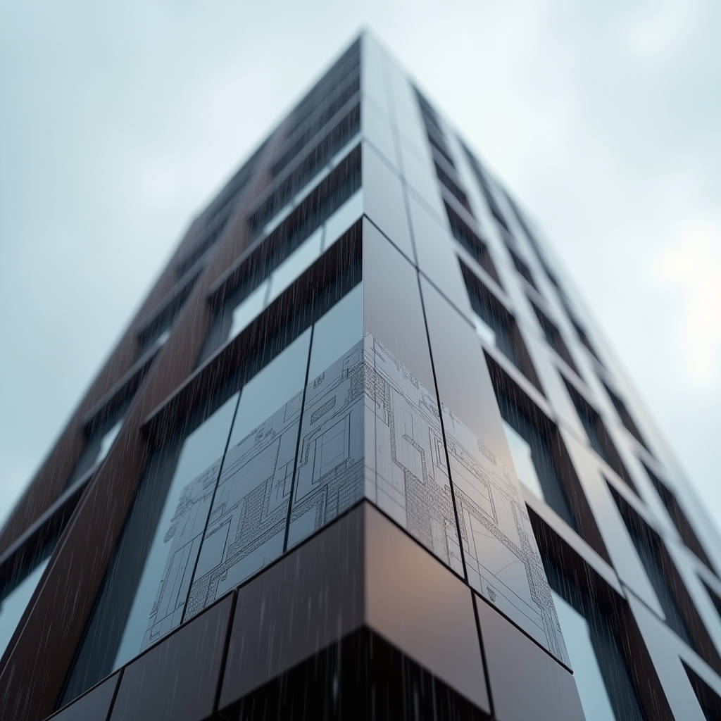
When a project team sits down to review cladding options for a new office tower, the conversation rarely stays on aesthetics for long. Within the first ten minutes, someone asks about wind. Not the abstract kind — the kind that peels poorly anchored panels off a 22nd-floor spandrel zone during a winter storm. Office building exterior panels live in a brutal aerodynamic environment, and the difference between a 20-year facade and a liability claim often comes down to how well the engineering team understood the wind loads at each elevation. This article walks through the structural logic, the code requirements, and the practical decisions that determine whether your aluminium cladding stays put when the pressure differentials spike.
Why Wind Load Drives Every Decision on Office Building Exterior Panels
Wind is not a uniform force. It accelerates around corners, creates negative suction zones on leeward faces, and channels through urban canyons at speeds that can exceed the design values pulled from a regional wind map. For office building exterior panels, the critical parameter is not the average wind speed — it is the peak gust pressure acting on specific zones of the building envelope. ASCE 7-22 defines these zones clearly. Zone 5, the corner zones, can experience pressures 2.5 to 3 times higher than the field area of the same wall. A panel that performs flawlessly in the middle of a facade may fail catastrophically at the building edge if the substructure and fastener schedule were designed to a single, averaged value.
Most curtain wall consultants now specify wind loads using the Components and Cladding (C&C) method rather than the Main Wind Force Resisting System (MWFRS) approach. C&C loads are higher because they account for localized peak pressures on individual panels. For a 100-meter-tall office building in a coastal city, C&C design pressures can easily reach 3.5 kPa to 5.0 kPa on corner panels. That translates to roughly 350 to 500 kg of force per square meter — reversing direction as the wind gusts and relaxes. Solid aluminium panels at 2.5mm or 3.0mm thickness can handle these loads, but only if the fixing system is engineered to match.
Field Note: On a project in Singapore, we saw corner panels specified at 2.0mm thickness across the entire facade. The wind tunnel report showed Zone 5 pressures hitting 4.2 kPa. The panel deflection under that load exceeded L/60 — visible to the naked eye from street level. The fix was straightforward: bump corner-zone panels to 3.0mm and reduce the stiffener spacing from 600mm to 400mm. The material cost increase was under 3% of the cladding package. The alternative was a facade that rippled every time the monsoon arrived.
Reading the Code: ASCE 7, EN 1991-1-4, and What They Mean for Aluminium Panels
Different jurisdictions use different wind loading codes, but the underlying physics is the same. ASCE 7-22 (United States), EN 1991-1-4 (Europe), and AS/NZS 1170.2 (Australia/New Zealand) all require designers to calculate peak velocity pressure, apply pressure coefficients based on building geometry, and then distribute those loads across the facade zones. The output is a set of design pressure values — positive for windward walls, negative (suction) for leeward walls and corners — that the cladding system must resist.
For solid aluminium office building exterior panels, the governing failure mode under wind is rarely the panel material itself. Aluminium 3003-H14 or 5052-H32 at 2.5mm thickness has a yield strength between 145 and 195 MPa. A properly stiffened panel spanning 600mm between supports can handle well over 5.0 kPa before reaching yield. The weak points are the connections: the rivets or screws fixing the panel to the subframe, the subframe anchors to the primary structure, and the inter-panel joints where wind-driven rain can penetrate if deflection opens a gap.
EN 1991-1-4 introduces the concept of peak velocity pressure qp(z), which incorporates both mean wind speed and short-term turbulence. For a 60-meter office building in terrain category III (urban), qp at the top can be around 1.8 kN/m². Apply a pressure coefficient cpe,10 of -1.4 for a corner zone, and the net design suction is 2.52 kN/m². That is the number the fixing engineer uses to size every anchor. Getting it wrong by 20% — say, by using the field-zone coefficient for corner panels — means the anchors are undersized by a factor that can lead to fatigue cracking over thousands of wind cycles.
Panel Thickness, Stiffener Layout, and the Deflection Limit
Aluminium panel thickness is not a standalone variable. It interacts with stiffener spacing, stiffener profile, and the allowable deflection limit specified in the project documents. The industry default for office building exterior panels is L/60 under design wind load, where L is the span between stiffeners or supports. Some architects push for L/90 or even L/120 on highly visible facades to eliminate any perceptible waviness under load. That tighter limit can drive panel thickness up or stiffener spacing down — and both have cost implications.
Consider a typical 1200mm x 3000mm panel with stiffeners running horizontally at 600mm centers. At 2.5mm thickness in alloy 3003-H14, the panel might deflect 9.5mm under a 3.0 kPa load — just within L/60 (10mm). If the spec requires L/90, the same panel needs to deflect less than 6.7mm. Achieving that might mean moving to 3.0mm thickness or adding an intermediate stiffener row. The table below shows how these variables interact for a typical office facade panel.
| Panel Thickness | Stiffener Spacing | Design Load | Deflection (mm) | Deflection Ratio | Meets L/60? | Meets L/90? |
|---|---|---|---|---|---|---|
| 2.0mm | 600mm | 3.0 kPa | 14.2 | L/42 | No | No |
| 2.5mm | 600mm | 3.0 kPa | 9.5 | L/63 | Yes | No |
| 3.0mm | 600mm | 3.0 kPa | 5.8 | L/103 | Yes | Yes |
| 2.5mm | 400mm | 3.0 kPa | 4.2 | L/143 | Yes | Yes |
| 3.0mm | 800mm | 3.0 kPa | 11.0 | L/73 | Yes | No |
The takeaway: specifying panel thickness without specifying stiffener layout and deflection criteria is meaningless. A 2.5mm panel with 400mm stiffener spacing outperforms a 3.0mm panel with 800mm spacing. The engineering team needs all three numbers on the same drawing, and the procurement team needs to understand that the lowest-thickness bid may not be the lowest-cost solution once stiffener and labor costs are factored in.
Fastener Fatigue: The Overlooked Failure Mode
Wind loads are not static. A typical office building in a temperate climate experiences tens of thousands of wind gust cycles per year. Each cycle applies a stress reversal to every fastener in the cladding system. Aluminium rivets and stainless steel screws both have fatigue limits, and if the cyclic stress exceeds a certain threshold, the fastener will eventually crack — not from a single overload event, but from the accumulated damage of thousands of small load cycles.
For office building exterior panels, the fatigue problem is most acute at corner zones and parapet edges where pressure fluctuations are largest. A panel that sees a design pressure of +3.0 kPa on the windward gust and -2.5 kPa on the leeward suction experiences a 5.5 kPa stress range per cycle. If the fastener was sized only for the maximum absolute pressure, the stress range may be overlooked. The fix is to specify fasteners with a fatigue rating appropriate for the expected cycle count over the building's design life — typically 50 years for commercial structures.
Stainless steel grade 316 (A4) fasteners are standard for aluminium cladding in corrosive environments. Their fatigue strength at 10⁷ cycles is roughly 150-180 MPa, depending on the specific alloy and manufacturing process. For a typical M6 fastener with a cross-sectional area of 20.1 mm², that translates to a fatigue load capacity of about 3.0 to 3.6 kN per fastener. If the wind load analysis shows that a corner panel requires four fasteners each carrying 1.2 kN under peak load, the fatigue margin is healthy. If the per-fastener load approaches 2.5 kN, the margin shrinks and the engineer should consider adding fasteners or upsizing to M8.
Pro Tip: Always request the fastener supplier's S-N curve (stress vs. number of cycles) for the specific material and diameter being used. Generic fatigue data from a textbook is not sufficient for a facade that will see 50 years of coastal wind cycles. If the supplier cannot provide an S-N curve for their fasteners, find a supplier who can. This single document has resolved more facade disputes than any other piece of engineering paperwork.
Substructure Design: The Gap Between Panel and Building
The aluminium panel itself is only one layer in the facade system. Behind it sits the substructure — typically aluminium extruded profiles or galvanized steel channels — that transfers wind loads from the panel to the building's primary structural frame. The substructure has its own deflection limits, its own thermal expansion requirements, and its own connection points that must be coordinated with the panel layout.
A common problem arises when the panel engineer and the substructure engineer work independently. The panel engineer assumes the substructure is rigid. The substructure engineer assumes the panel loads are distributed evenly. Neither assumption holds in reality. The substructure deflects under load, which changes the boundary conditions for the panel. The panel's stiffeners concentrate loads at specific points, which the substructure must handle as point loads rather than uniform loads. The result, if not coordinated, is a system that meets the letter of the specification but performs poorly in the field — with rattling panels, visible misalignment at joints, and water ingress at deflected seals.
For office building exterior panels, the substructure should be designed to a deflection limit of L/360 under the combined panel loads. This is tighter than the panel deflection limit of L/60 because substructure deflection directly affects panel alignment and joint performance. A 3mm deflection in a 3000mm-long mullion may be structurally acceptable but visually unacceptable when it creates a 3mm step between adjacent panels. Specifying a coordinated deflection budget — allocating, say, L/120 to the panel and L/360 to the substructure — prevents the two systems from fighting each other.
Thermal Movement: Why 3mm Gaps Matter
Aluminium expands and contracts with temperature. The coefficient of linear thermal expansion for aluminium 3003 is approximately 23.2 x 10⁻⁶ per °C. A 3000mm panel subjected to a 60°C temperature swing (from -10°C in winter to +50°C on a sun-exposed dark facade in summer) will change length by about 4.2mm. If the panel joints do not accommodate this movement, the panels will buckle on hot days or pull apart on cold ones.
The standard joint width for office building exterior panels is 8mm to 12mm, sealed with a weather-grade silicone sealant capable of ±25% movement accommodation. At 10mm joint width, the sealant can handle ±2.5mm of movement. The panel's thermal movement of ±2.1mm falls within this range, but only just. If the building is in a climate with larger temperature swings, or if the panels are longer than 3000mm, the joint width needs to increase proportionally. A 4000mm panel in the same climate needs a 12mm joint to stay within the sealant's movement capability.
This is not a theoretical concern. We have seen facades where panels were installed tight against each other in winter, only to buckle outward by 8mm when summer sun hit the dark PVDF coating. The fix involved removing every panel, trimming the edges, and reinstalling with proper gaps — at a cost that exceeded the original cladding contract value. The engineering lesson is simple: thermal movement calculations are not optional, and they must account for the actual surface temperature of the panel, not just the ambient air temperature. A dark-colored panel in direct sunlight can be 20°C to 30°C hotter than the surrounding air.
PVDF Coating Performance Under Wind-Driven Conditions
Wind does not just load the panel structurally. It also drives rain, dust, and salt spray against the coating at high velocity. A PVDF (polyvinylidene fluoride) coating based on Kynar 500® resin is the industry standard for office building exterior panels because it resists chalking, fading, and chemical degradation under these conditions. But not all PVDF coatings are equal, and the specification details matter.
A proper architectural PVDF coating contains a minimum of 70% PVDF resin by weight in the color coat, with the balance being acrylic resin for pigment dispersion and adhesion. The total dry film thickness should be 30-35 microns for a two-coat system (primer + color) or 40-45 microns for a three-coat system (primer + color + clear). Coatings that skimp on PVDF content — using 50% or less — will show measurable color shift (Delta E > 3) within 5-7 years in exposed locations. A full Kynar 500® three-coat system should maintain Delta E < 2 after 10 years of south-facing exposure, per AAMA 2605 testing requirements.
The wind-driven rain aspect is often overlooked. At wind speeds above 15 m/s, rain droplets carry enough kinetic energy to erode a low-quality coating over time. This is particularly relevant for office buildings in coastal or monsoon climates. The AAMA 2605 specification includes a 4000-hour accelerated weathering test (ASTM G155) that simulates this combined UV and moisture exposure. Panels that pass this test with Delta E below 5 are suitable for the most demanding exterior applications. Suppliers like Futeng® provide AAMA 2605-compliant PVDF coatings as standard for their solid aluminium cladding panels, with full test reports available for each production batch — a documentation requirement that has become non-negotiable for specification-grade office projects.
Wind Tunnel Testing vs. Code Calculations: When to Invest
Building codes provide conservative wind load estimates based on simplified building shapes and generic terrain categories. For a rectangular office tower in a suburban setting, code calculations are usually sufficient. But when the building has an unusual geometry — curved facades, deep recesses, rooftop screens, or a location in a dense urban cluster — wind tunnel testing becomes the only reliable way to determine the actual pressure distribution.
Wind tunnel testing for cladding design typically costs between $30,000 and $80,000, depending on the building complexity and the number of pressure taps. That sounds expensive until you compare it to the cost of over-engineering the entire facade to code-level loads that may be 30-40% higher than the actual wind pressures. On a large office project with 15,000 m² of cladding, reducing the design pressure by 1.0 kPa through wind tunnel data can save $200,000 to $400,000 in panel thickness, stiffener material, and anchor hardware. The test pays for itself several times over.
The wind tunnel report provides pressure coefficient maps for the entire building envelope, broken down into zones that are typically finer than the code zones. This allows the engineering team to optimize panel specification zone by zone — using 3.0mm panels only where the pressures demand them, and 2.5mm or even 2.0mm panels in low-pressure field areas. The material savings from this zoned approach, combined with the reduced risk of under-designing corner panels, makes wind tunnel testing a standard recommendation for any office building over 80 meters in height or with a complex facade geometry.
Practical Specification Checklist for Wind-Resistant Aluminium Cladding
Based on the engineering principles outlined above, here is a concise checklist that project teams can use when specifying office building exterior panels for wind-critical applications:
- Confirm the design wind load standard: ASCE 7-22, EN 1991-1-4, or local equivalent. Verify the basic wind speed, terrain category, and importance factor with the project's structural engineer of record.
- Request the C&C pressure zone map: Do not accept a single design pressure for the entire facade. Corner zones, edge zones, and field zones have different pressure coefficients and must be specified separately.
- Specify panel thickness by zone: 2.5mm minimum for field zones, 3.0mm for corner and edge zones on buildings over 60 meters. Adjust based on stiffener layout and deflection criteria.
- Define the deflection limit: L/60 is the industry minimum. L/90 or L/120 is appropriate for high-visibility facades. Include both the panel deflection limit and the substructure deflection limit in the specification.
- Require fatigue-rated fasteners: Stainless steel 316 (A4) with documented S-N curves. Calculate the per-fastener load range under cyclic wind and verify it falls below the fatigue limit for the expected cycle count.
- Calculate thermal movement: Use the panel material's coefficient of thermal expansion and the local temperature range. Size joints and sealant accordingly.
- Specify PVDF coating to AAMA 2605: Minimum 70% PVDF resin, three-coat system for exposed locations. Require batch-specific test reports for color consistency and weathering performance.
- Consider wind tunnel testing: For buildings over 80m, complex geometries, or dense urban sites. The cost of testing is typically recovered through material optimization.
Wind loads are not the most glamorous topic in facade design. They do not appear in architectural renderings. No client ever walked through a lobby and complimented the fastener fatigue calculations. But every office building facade that has failed — that has leaked, buckled, rattled, or shed panels onto the street below — failed because someone treated wind as a simple number on a specification sheet rather than the complex, dynamic, and unforgiving force that it is. The engineering is not difficult. It just requires attention to detail, a willingness to zone the facade properly, and the discipline to verify every component from panel to fastener to sealant against the actual pressures the building will face. For the teams that do this work thoroughly, office building exterior panels deliver decades of quiet, reliable performance. For those that do not, the wind eventually finds every shortcut.