How Thermal Movement Dictates Joint Design for Shopping Mall Metal Panels
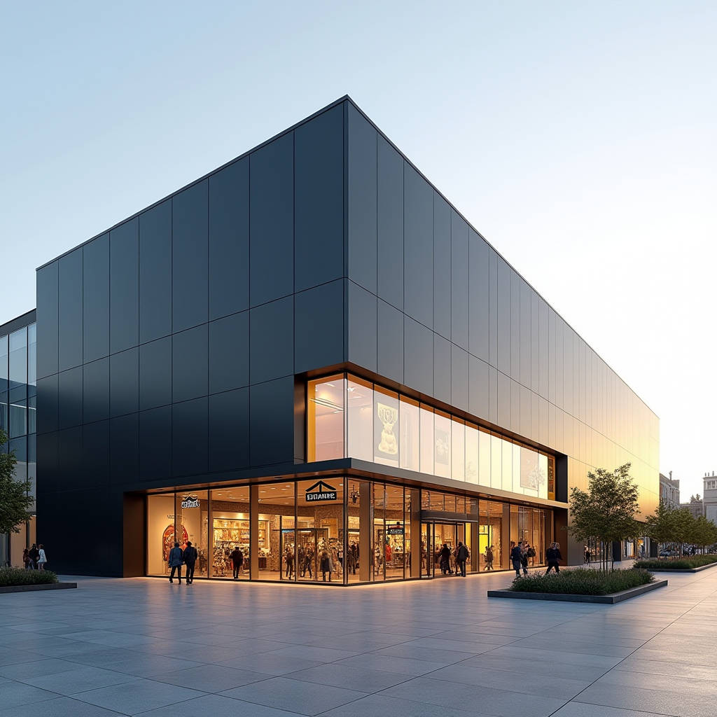
When a shopping mall facade starts showing hairline cracks around fastener penetrations six months after handover, the root cause is rarely the aluminium itself. More often, it traces back to a single overlooked calculation: thermal expansion. Solid aluminium cladding panels—typically 2.5mm to 3.0mm thick AA3003 or AA5052 alloy sheets—move. They expand under midday sun and contract during cold nights. On a 300-meter-long mall elevation, ignoring this movement does not just cause aesthetic headaches. It triggers panel buckling, gasket failure, water ingress, and ultimately, a call from the client that no contractor wants to field. This article examines how thermal movement governs the specification, joint design, and long-term performance of shopping mall metal panels, and why the conversation belongs at the front end of the design phase, not the punch list.
The Physics Every Mall Facade Engineer Should Know
Aluminium has a linear thermal expansion coefficient of approximately 23.4 × 10⁻⁶ m/m/°C. That number looks abstract on a datasheet. Translate it into a real scenario and the stakes become clear. Take a single 1200mm-wide solid aluminium panel installed at an ambient temperature of 20°C. On a summer afternoon in Dubai or Riyadh, the dark PVDF-coated surface can reach 80°C. That 60°C delta produces roughly 1.7mm of linear expansion per panel. Multiply that across 250 panels on a continuous facade run, and the cumulative movement exceeds 400mm.
The problem is not the movement itself. Aluminium is ductile and can handle stress. The problem is what happens when the movement has nowhere to go. Panels that are rigidly fixed at both ends, with no accommodation for slip, will buckle. Fasteners will ovalize their holes. Sealant joints will tear. The damage is progressive and expensive.
ASTM E228 provides the standard test method for linear thermal expansion of solid materials. But knowing the coefficient is only step one. The engineering task is designing joints that absorb this movement without compromising weathertightness or visual uniformity. For shopping mall metal panels, this means joint widths are not aesthetic choices—they are mathematical outputs.
Joint Width Calculation: A Practical Framework
Most facade specifications for shopping mall applications reference a minimum joint width of 10mm to 12mm for standard panel sizes. But that number is meaningless without context. The correct joint width depends on four variables: panel dimension, expected temperature range, the expansion coefficient of the aluminium alloy, and the movement capability of the selected sealant.
The basic formula used across the industry is:
Minimum Joint Width = (Movement × 100) / (Sealant Movement Capability %) + Safety Factor
For a 1500mm panel experiencing a 70°C temperature swing, the calculated movement is approximately 2.46mm. Using a high-performance silicone sealant with ±50% movement capability, the theoretical minimum joint is about 5mm. But no responsible engineer stops there. A safety factor of 1.5 to 2.0 is standard, accounting for installation tolerances, substrate movement, and long-term sealant aging. The result: a specified joint of 10mm to 12mm, which aligns with what experienced facade contractors have been doing for decades.
This is where the specification of shopping mall metal panels intersects with sealant selection. Silicone sealants with ±50% movement capability are the industry baseline. For high-movement joints on large mall elevations, some engineers specify ±100% capability products. These come at a premium but reduce the required joint width, which can be desirable for architects pursuing a monolithic look.
| Panel Width (mm) | Temperature Range (°C) | Calculated Movement (mm) | Sealant Capability | Minimum Joint Width (mm) | Recommended Joint (mm) |
|---|---|---|---|---|---|
| 1000 | -10 to 70 | 1.87 | ±50% | 3.7 | 8 |
| 1200 | -10 to 70 | 2.25 | ±50% | 4.5 | 10 |
| 1500 | -10 to 70 | 2.81 | ±50% | 5.6 | 10 |
| 1500 | -20 to 80 | 3.51 | ±50% | 7.0 | 12 |
| 2000 | -10 to 70 | 3.74 | ±50% | 7.5 | 12 |
| 2000 | -20 to 80 | 4.68 | ±100% | 4.7 | 10 |
The table above assumes AA3003 alloy and a baseline installation temperature of 20°C. For projects in extreme climates—Scandinavian winters, Gulf summers—the temperature range should be adjusted based on local meteorological data, not generic assumptions. AAMA 501.5 provides guidance on thermal cycling testing for wall assemblies, and it is worth referencing in project specifications.
Fixing Systems: The Difference Between Restrained and Released
Joint width is only half the equation. The other half is how the panel is attached to the substructure. There are two fundamental approaches to fixing shopping mall metal panels: restrained systems and released systems. The choice between them determines whether the thermal movement is absorbed at the joint or at the fixing point.
Restrained (Fixed-Point) Systems
In a restrained system, each panel has one fixed anchor point—typically at the center or top edge—and all other attachment points use slotted holes that allow directional movement. The panel is pinned at one location and free to expand outward from that point. This is the most common approach for large-format solid aluminium panels on mall facades. The fixed point prevents the panel from "walking" over time while accommodating thermal movement through the slotted connections.
The slot dimensions must be calculated, not guessed. For a panel expected to move 2.5mm in one direction, the slot needs to provide at least 3mm of travel after accounting for bolt diameter and installation tolerance. Undersized slots are functionally equivalent to rigid fixing—they defeat the purpose.
Released (Cassette) Systems
Cassette or hook-on systems take a different approach. The panel hangs on a rail or clip system, usually with interlocking edges. The panel is not mechanically fastened through its face. Thermal movement is absorbed at the interlocking joints and through the clearance between the panel and the supporting rail. These systems are faster to install and provide cleaner sightlines, but they require tighter fabrication tolerances. A 1mm deviation in fold dimensions across 500 panels adds up to visible misalignment on a mall elevation.
Field Note: On a 2023 mall retrofit in Southeast Asia, the contractor used a cassette system with 2.5mm solid aluminium panels. The shop drawings specified a 3mm gap between the panel return leg and the support rail. During installation in 35°C heat, crews reported panels "sticking" and not seating properly. The issue: the gap was calculated for a 20°C installation temperature. At 35°C, the panels had already expanded, reducing the effective clearance. The fix was simple—increase the gap to 5mm—but it cost three weeks of rework. Always specify the installation temperature window in the method statement.
Substructure Compatibility: Steel, Aluminium, and the Galvanic Trap
The substructure that supports shopping mall metal panels is typically either hot-dip galvanized steel or extruded aluminium. Both work. Both have trade-offs. What matters is that the interface between the panel and the substructure does not create a galvanic corrosion cell.
Solid aluminium panels (AA3003/AA5052) have a corrosion potential of approximately -0.83V versus a saturated calomel electrode. Hot-dip galvanized steel sits at roughly -1.02V. The potential difference is about 0.19V, which is below the 0.25V threshold generally considered acceptable for outdoor exposure without isolation. In practice, however, most facade specifications still require a physical barrier—typically a PVC or EPDM isolating pad—between the aluminium panel and the steel substructure. This is belt-and-suspenders engineering, but it is cheap insurance against a problem that is expensive to fix.
When the substructure is aluminium, the galvanic risk disappears, but thermal movement becomes a shared problem. Both the panel and the rail expand and contract. If the rail is continuous and rigidly fixed to the building structure, its movement may differ from the panel's movement, creating shear stress at the connection points. The solution: design the rail system with expansion joints that align with the panel joints. This is standard practice in curtain wall design but sometimes overlooked in rainscreen cladding for retail buildings.
PVDF Coatings Under Thermal Stress
Thermal movement does not just affect the aluminium substrate. It also stresses the coating system. For shopping mall metal panels, the industry standard is a PVDF (polyvinylidene fluoride) coating based on Kynar 500® or Hylar 5000® resin, applied at a minimum 70% resin-to-pigment ratio. This coating system is specified at a dry film thickness of 25-35μm for a two-coat system and 35-45μm for a three-coat system.
PVDF coatings are formulated to handle thermal cycling. AAMA 2605, the highest performance standard for architectural coatings on aluminium, requires passing a 10-year South Florida exposure test with a maximum Delta E color shift of 5.0 and a maximum gloss retention of 50%. But even the best coating can fail if the substrate moves excessively and the coating cannot follow.
The elongation at break for a typical PVDF coating is 20-30%. That sounds generous until you consider that the coating is bonded to a substrate that expands and contracts. The coating must match the substrate's movement without cracking, delaminating, or losing adhesion. This is tested through impact resistance, bend testing, and cyclic weathering per AAMA 2605. When specifying shopping mall metal panels, the coating certification should be requested alongside the panel material certification. The two are a system, not separate purchases.
Color Selection and the Solar Absorption Variable
Dark-colored panels absorb more solar radiation. A black PVDF-coated panel can reach a surface temperature 25-30°C higher than a white panel under the same conditions. This directly increases thermal movement. A 1500mm dark panel in full sun might move 3.5mm, while an identical white panel moves 2.5mm. The joint design must account for the worst case, not the average.
This is particularly relevant for shopping mall metal panels because mall facades often use bold, dark accent colors for branding and visual impact. The architect selects a deep charcoal or navy blue, and the engineer must then adjust the joint widths and fixing details to accommodate the higher thermal load. If the specification treats all colors the same, the dark panels will be the first to show problems.
Total Solar Reflectance (TSR) data is available from PVDF coating manufacturers for every color in their range. AAMA 2605-compliant coatings with high TSR values can reduce surface temperature by 10-15°C compared to standard formulations. For projects in hot climates, specifying a cool-roof-type PVDF with enhanced TSR can reduce thermal movement, lower cooling loads, and extend coating life. The cost premium is modest—typically 5-8% on the coating line item—and the payback in reduced maintenance is real.
Wind Load and Thermal Movement: The Combined Effect
Facade engineers are trained to calculate wind loads per ASCE 7 or the local building code equivalent. Thermal movement is calculated separately. But the two forces act simultaneously. A panel that has expanded under solar heating is also being pushed and pulled by wind pressure. The combined stress at the fixing points can exceed the sum of the individual stresses because the panel's geometry has changed.
For shopping mall metal panels, the critical load case is often a hot, windy afternoon. The panel is at maximum expansion, the wind is gusting, and the fixing system must accommodate movement while resisting load. This is where the choice of fixing system matters most. Restrained systems with slotted holes must be designed so that the slot orientation does not compromise wind load resistance. A slot that allows horizontal movement should not reduce the vertical load capacity of the connection.
The interaction between thermal and wind loads is addressed in AAMA 508, which provides a test method for pressure-equalized rainscreen systems. While not every mall project requires full pressure-equalization, the testing methodology is useful for validating the combined performance of the panel, joint, and fixing system.
Pro Tip: When reviewing shop drawings for shopping mall metal panels, check the slot orientation relative to the panel's fixed point. Slots should radiate outward from the fixed point, not all run in the same direction. A common drafting error is to show all vertical slots aligned identically, which effectively locks the panel against horizontal expansion. This is the kind of detail that looks fine on paper and fails in the field.
Fabrication Tolerances and Their Impact on Joint Performance
A joint designed for 10mm does not help if the fabricated panel is 2mm oversize. The panel eats into the joint, reducing the effective movement capacity. This is why fabrication tolerances for shopping mall metal panels must be tight and must be verified.
Industry-standard tolerances for solid aluminium cladding panels are typically ±1.0mm on length and width dimensions for panels up to 1500mm, and ±1.5mm for panels up to 2500mm. Diagonal tolerance—the difference between the two diagonal measurements—should be within 2.0mm for panels up to 1500mm and 3.0mm for larger panels. Fold angle tolerances are ±1.0°.
These numbers come from a combination of ISO 2768 (general tolerances) and project-specific facade specifications. For cassette systems, the tolerances are tighter because the panels must interlock. A 1.5mm deviation on a 1200mm cassette panel can create a visible step at the joint, even if the joint itself is structurally adequate.
Futeng® and other established manufacturers of solid aluminium panels maintain these tolerances through CNC folding equipment and quality control checkpoints at each fabrication stage. For the contractor, the key is to verify: request dimensional inspection reports with each batch, and conduct spot checks on site before installation begins. Finding a tolerance issue after 200 panels are on the wall is a costly discovery.
Packaging, Transport, and the Thermal Dimension
Thermal considerations extend beyond the installed facade. Solid aluminium panels in transit can experience temperature swings that cause temporary distortion. A stack of panels shipped from a factory in a temperate climate to a project site in the tropics can arrive with visible warping. This is usually reversible—the panels relax as they acclimate to the ambient temperature—but it can cause panic on site if the receiving team is not forewarned.
Proper packaging mitigates this. Panels should be packed with protective interleaving, on A-frame crates that allow air circulation. The crates should be stored in shaded areas on site for 24-48 hours before installation, allowing the panels to reach thermal equilibrium with the installation environment. This is a simple step that is often skipped in the rush to meet the program.
For international shipments, the packaging specification should account for the full journey: factory to port, ocean freight, destination port, and truck to site. The crate design must handle the mechanical loads of handling and the thermal loads of climate transition. A panel that leaves the factory flat and arrives on site bowed is not a material defect—it is a packaging failure.
Putting It Together: A Specification Checklist for Thermal Movement
For the contractor or specifier preparing a bid package for shopping mall metal panels, the following items should be addressed in the specification or the pre-construction submission:
- Temperature range basis: Specify the design temperature range based on local climate data, not generic values.
- Joint width calculation: Require the facade contractor to submit joint width calculations for each panel size and color, referencing the sealant's tested movement capability.
- Fixing system type: Define whether restrained or released, and require slot dimension calculations for restrained systems.
- Galvanic isolation: Specify isolating pads or washers at all aluminium-to-steel interfaces.
- Coating certification: Require AAMA 2605 certification for PVDF coatings, including TSR data for dark colors.
- Fabrication tolerances: Reference ISO 2768-m or tighter, and specify dimensional inspection requirements.
- Installation temperature window: Define the acceptable ambient temperature range for panel installation, and require the contractor to record temperatures during installation.
- Mock-up testing: Require a visual mock-up that includes at least two full panel bays and one expansion joint, installed and inspected before production begins.
This checklist is not exhaustive, but it covers the thermal movement issues that are most frequently overlooked in mall facade projects. The cost of addressing these items during design is measured in engineering hours. The cost of ignoring them is measured in replacement panels, scaffold hire, and liquidated damages.
Thermal movement is not a complex topic. The physics is straightforward, the calculations are simple, and the solutions are well-established. What makes it a recurring problem on shopping mall metal panels is not the difficulty of the engineering—it is the tendency to treat joint design as a detailing afterthought rather than a core performance requirement. The panels will move. The only question is whether the facade system is designed to let them.