Residential Metal Paneling Rainscreen Cavity Design and Drainage Engineering
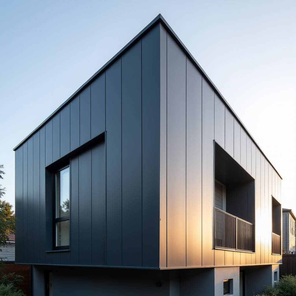
When a general contractor asks about residential metal paneling, the first question is rarely about the panel itself. It is about the wall behind it. Specifically, how the cladding handles moisture, thermal movement, and the drainage plane over a 50-year service life. Most residential facade failures we investigate trace back to one thing: the rainscreen cavity was either missing, undersized, or blocked by careless detailing. The panel is almost never the root cause. But the panel system—how it connects to the substructure, how it breathes, and how it sheds water—determines whether the assembly succeeds or fails. This article examines the engineering fundamentals of ventilated rainscreen design with solid aluminium cladding panels in residential applications, focusing on cavity depth, clip thermal isolation, and the drainage calculations that keep interior framing dry across decades of seasonal cycling.
Why Residential Walls Fail Before the Panel Does
Walk around a five-year-old residential project with metal cladding and look closely at the corners. If you see efflorescence staining on the concrete sill, rust bleeding from fastener heads, or paint blistering along the bottom edge, the panel is fine. The water management has failed. Solid aluminium panels—2.5 mm or 3.0 mm thick, PVDF-coated, fabricated to tight tolerances—do not absorb water. They do not rot. They do not delaminate. But they also do not forgive poor cavity design. Water that gets past the panel face, whether through open joints, capillary action at panel laps, or condensation on the back side of the metal, must have a clear path down and out. Without a properly dimensioned cavity, that water sits against the weather barrier, finds a fastener penetration, and migrates inward. The repair cost dwarfs the original cladding budget.
ASTM E2924 defines standard practices for testing water penetration through exterior wall assemblies. The standard exists because the problem is widespread. In residential metal paneling installations, the stakes are higher than in commercial work. Occupants live inches from the wall. They notice damp drywall. They smell mold long before anyone sees a stain. The cavity behind the panel is not a nice-to-have detail. It is the primary drainage layer.
Ventilated Rainscreen Principles Applied to Residential Metal Paneling
A ventilated rainscreen separates four functions: the outer cladding (weather screen), the ventilation and drainage cavity, the water-resistive barrier (WRB), and the structural backup wall. Each layer has one job. The panel deflects direct rain and UV. The cavity neutralizes wind-driven moisture by equalizing pressure and allowing gravity drainage. The WRB stops any water that reaches it. The backup wall carries structural loads. When one layer tries to do the job of another, the system fails.
For residential metal paneling using solid aluminium sheets, the cavity must be at least 19 mm (3/4 inch) deep per the International Building Code (IBC) Section 1402.2 for drained and vented cladding systems. But 19 mm is a minimum, not an optimum. In coastal residential projects where wind-driven rain is frequent, we specify 25 mm to 38 mm cavity depths. The deeper cavity allows faster drainage, better ventilation drying, and more tolerance for framing irregularities. Residential wood-framed walls are rarely as flat as commercial steel stud walls. A 6 mm out-of-plane stud over a 3-meter wall height can choke a 19 mm cavity to near zero at the mid-span. That is where water traps form.
Field Note: On a residential rainscreen project in Vancouver, we found that the framing contractor had installed the WRB with staples spaced 150 mm apart. Each staple penetration became a leak point when the cavity was only 16 mm deep and partially blocked by insulation bulging. The fix required removing all panels, replacing the WRB with a self-adhered membrane, and increasing the cavity to 32 mm using thermally broken aluminium hat channels. The material cost increase was roughly $12 per square meter. The rework cost exceeded $180,000.
Cavity Depth Calculation: More Than a Code Minimum
Designing the cavity for residential metal paneling involves balancing three variables: drainage capacity, ventilation drying, and constructability. The drainage capacity must handle the maximum expected wind-driven rain infiltration rate. For a 4-storey residential building with open-joint aluminium panels, a reasonable assumption is that 1% to 3% of wind-driven rain will penetrate the panel face. On a wall area of 200 m², with a design rain intensity of 2 liters per minute per m², the cavity must drain 4 to 12 liters per minute. A 19 mm cavity with a 10 mm drainage gap at the base can handle approximately 8 liters per minute per meter of wall width. At 25 mm, the capacity roughly doubles due to reduced surface tension effects.
Ventilation drying is the second function. The cavity must allow enough air movement to evaporate residual moisture between rain events. ASHRAE 160 provides criteria for moisture control analysis. The key parameter is the ventilation rate, measured in air changes per hour within the cavity. A 25 mm cavity with open top and bottom vents achieves roughly 15 to 30 air changes per hour under typical wind conditions. This is sufficient to dry the cavity within 24 to 48 hours after a rain event in most climates. In humid subtropical regions, increasing cavity depth to 38 mm and adding mid-wall vents improves drying performance measurably.
The table below summarizes cavity depth recommendations based on exposure conditions and backup wall type for residential metal paneling applications.
| Exposure Condition | Backup Wall Type | Minimum Cavity Depth | Recommended Cavity Depth | Ventilation Configuration |
|---|---|---|---|---|
| Low-rise, sheltered site | Steel stud / concrete | 19 mm | 25 mm | Bottom and top vents |
| Mid-rise, urban exposure | Wood stud / steel stud | 25 mm | 32 mm | Bottom, top, and mid-wall vents |
| Coastal, high wind-driven rain | Wood stud / CLT | 32 mm | 38 mm | Continuous vented cavity, open joints |
| Cold climate (Zone 6+) | Wood stud / steel stud | 25 mm | 32 mm | Bottom and top vents, insect screen |
| Mixed-humid climate | Any backup wall | 25 mm | 32 mm | Bottom, top, and mid-wall vents |
Clip and Substructure Thermal Isolation
When you attach solid aluminium cladding panels to a residential wall, the clips and subframe create thermal bridges. Each aluminium clip that passes from the panel side through the insulation layer to the structural backup wall conducts heat. In a heating-dominated climate, the clip tip temperature drops below the dew point. Condensation forms on the clip. That moisture drips into the insulation or onto the WRB. Over time, the clip corrodes, the insulation loses R-value, and the wall assembly degrades.
Thermally broken clips solve this problem. A thermal break—typically a 6 mm to 12 mm thick pad of glass-fiber-reinforced polyamide or rigid PVC—sits between the aluminium clip body and the structural attachment point. The thermal conductivity of polyamide is roughly 0.25 W/m·K, compared to 160 W/m·K for aluminium. The break reduces heat flow through the clip by over 90%. For residential metal paneling in climates with more than 3,000 heating degree days, thermally broken clips are not optional. They are essential to prevent interstitial condensation.
The cost premium for thermally broken clips runs approximately $3 to $6 per clip, which translates to $8 to $15 per square meter of wall area depending on clip spacing. For a 300 m² residential facade, the total added cost is $2,400 to $4,500. Compare that to the cost of removing and replacing rotted sheathing and mold-damaged insulation five years after occupancy. The economics are straightforward.
Futeng® supplies solid aluminium cladding panels with engineered clip systems that integrate thermal break options. The clip design allows for 3-axis adjustment during installation, which is critical when the backup wall is out of tolerance. Residential framing crews rarely achieve the ±3 mm flatness that commercial curtain wall installers deliver. The adjustable clip absorbs that variance without stressing the panel or compromising the cavity depth.
Drainage Plane Continuity: The Weakest Link
The drainage plane behind residential metal paneling is only as good as its weakest detail. Window openings, balcony penetrations, meter boxes, and vent terminations all interrupt the cavity. At each interruption, water must be directed around the opening and back into the drainage plane below. If the flashing at a window head does not extend past the window jambs by at least 150 mm, water runs off the flashing edge and into the rough opening. If the sill flashing does not slope outward at a minimum of 6 degrees, water ponds against the window frame.
At the base of the wall, the cavity must terminate with a continuous insect screen and a drip edge that projects at least 10 mm beyond the face of the backup wall. The drip edge prevents water from wicking back into the wall assembly. In residential projects, we often see the base detail omitted or replaced with a simple J-trim that traps water. The J-trim creates a dam at the bottom of the cavity. Water backs up, finds the fastener penetrations, and enters the wall. A proper base detail uses an L-shaped flashing with a hemmed drip edge, continuous perforated closure, and a 10 mm gap between the panel bottom and the flashing to allow free drainage and air intake.
Pro Tip: When specifying residential metal paneling for projects with wood-framed backup walls, require the WRB to be fully installed and inspected before the cladding subframe begins. Take photos of every penetration, every window flashing, and every transition detail. These photos become the only record of the drainage plane once the panels go up. On a project in Seattle, these photos saved the contractor $40,000 in legal costs when the owner alleged water intrusion two years after completion. The photos proved the WRB was intact and the cavity was clear at the time of panel installation.
Material Selection for the Rainscreen Cavity Environment
The environment inside a rainscreen cavity is surprisingly aggressive. Temperatures can swing from -20°C to +80°C in a single year depending on climate and panel color. Relative humidity ranges from 10% to 100% within hours. The cavity sees UV light at open joints. Fasteners and subframe components must withstand these conditions for the life of the building.
For solid aluminium cladding panels in residential metal paneling applications, the panel material itself is straightforward: 3003-H14 or 5052-H32 aluminium alloy, 2.0 mm to 3.0 mm thick, with a PVDF coating system meeting AAMA 2605. The coating contains a minimum 70% Kynar 500 or Hylar 5000 fluoropolymer resin by weight in the color coat. Dry film thickness is 25 to 35 microns for the color coat plus a clear coat for metallic finishes. This coating system has a documented 30-year service life in exterior exposure per AAMA testing.
The subframe material requires more careful specification. Aluminium extrusions for the subframe should be 6063-T6 alloy with a minimum 15-micron anodized finish (AA-M10C22A31 per AAMA 611) or a 60-micron minimum PVDF coating. Stainless steel fasteners—grade 304 for inland applications, grade 316 for coastal—are mandatory. Galvanized steel fasteners will corrode in the cavity environment within 5 to 10 years, especially in the presence of treated wood backup walls. The copper-based preservatives in pressure-treated lumber are highly corrosive to zinc coatings and carbon steel.
Wind Load and Clip Spacing Engineering
Residential metal paneling systems must resist wind loads that vary dramatically across the facade. The corner zones of a building experience suction pressures 2 to 3 times higher than the field of the wall. ASCE 7 provides the methodology for calculating design wind pressures based on building height, exposure category, and geographic location. For a typical 3-storey residential building in Exposure B (suburban terrain) with a basic wind speed of 150 km/h (93 mph), the design pressure in corner zones can reach 1.8 kPa (38 psf). The field of wall might see only 0.8 kPa (17 psf).
Clip spacing must be engineered for the worst-case zone. A typical aluminium clip for 3.0 mm solid panels, spaced at 600 mm on center vertically and horizontally, can resist approximately 2.5 kPa of wind pressure with a safety factor of 2.0. In corner zones, clip spacing should be reduced to 400 mm or 450 mm on center. The panel itself must also be checked for deflection under wind load. For residential metal paneling, the allowable deflection is typically L/175 for the panel span between clips, where L is the span in millimeters. A 3.0 mm thick aluminium panel spanning 600 mm between clips will deflect approximately 3.4 mm under a 1.8 kPa load, which is within the L/175 limit. A 2.0 mm panel under the same conditions deflects approximately 7.6 mm, exceeding the limit and requiring reduced clip spacing.
The following table provides recommended maximum clip spacings for solid aluminium panels under various wind load conditions.
| Panel Thickness | Wind Zone | Design Pressure | Max Clip Spacing (Vertical) | Max Clip Spacing (Horizontal) |
|---|---|---|---|---|
| 2.0 mm | Field of wall | ≤ 1.0 kPa | 500 mm | 600 mm |
| 2.0 mm | Corner zone | ≤ 2.0 kPa | 350 mm | 450 mm |
| 2.5 mm | Field of wall | ≤ 1.5 kPa | 600 mm | 600 mm |
| 2.5 mm | Corner zone | ≤ 2.5 kPa | 400 mm | 500 mm |
| 3.0 mm | Field of wall | ≤ 2.0 kPa | 600 mm | 600 mm |
| 3.0 mm | Corner zone | ≤ 3.0 kPa | 450 mm | 500 mm |
Thermal Movement Accommodation
Aluminium expands and contracts at a rate of approximately 0.024 mm per meter per degree Celsius. A 4-meter-long panel on a south-facing residential wall in Denver can experience a surface temperature swing from -15°C on a winter night to +70°C under direct summer sun. That is an 85°C delta. The thermal movement of the panel is 4 × 0.024 × 85 = 8.16 mm. If the panel is fixed rigidly at all four corners, that 8 mm of movement must go somewhere. It will either buckle the panel, shear the fasteners, or crack the coating at the fixed points.
The solution is a combination of fixed and sliding clip points. Each panel has one fixed point—typically near the center—that restrains the panel in all three axes. All other clip points are sliding points that allow movement in the plane of the panel. The sliding clips use elongated holes or slotted connections that permit the calculated thermal movement plus a safety margin. For residential metal paneling, the sliding connection should accommodate at least ±6 mm of movement in both the vertical and horizontal directions for panels up to 4 meters in length. Longer panels require proportionally more travel.
Joint width between panels must also accommodate thermal movement. The minimum joint width is 6 mm for panels up to 2 meters, 8 mm for panels up to 3 meters, and 10 mm for panels up to 4 meters. These joint widths also serve as the air intake for the ventilated cavity, so they serve a dual function. Open joints—where the joint is left open without sealant—are increasingly common in residential metal paneling because they eliminate sealant maintenance and maximize cavity ventilation. The trade-off is that open joints allow more water penetration, which increases the drainage demand on the cavity. The cavity design must account for this.
Quality Control During Installation
The best rainscreen design on paper fails if the installation is sloppy. For residential metal paneling projects, the critical inspection points are: cavity depth verification at every clip location, WRB continuity at all penetrations, clip attachment torque, and panel joint alignment. Cavity depth should be checked with a go/no-go gauge at each clip before panels are installed. Any location where the cavity is less than the specified minimum must be corrected by adjusting the clip or shimming the subframe.
Clip attachment torque matters because over-torqued fasteners can strip the threads in the aluminium subframe or crush the thermal break pad. Under-torqued fasteners allow clip movement under wind load, which causes panel rattling and long-term fatigue. The correct torque for a typical M6 stainless steel fastener into an aluminium extrusion is 8 to 10 N·m. This should be verified with a calibrated torque wrench on a sample of fasteners at the start of each day's installation.
Panel joint alignment affects both aesthetics and water management. A misaligned joint creates a ledge where water can collect and run sideways instead of draining down the cavity. The industry tolerance for panel joint alignment in residential metal paneling is ±2 mm over any 3-meter length. Achieving this requires a properly set out grid, accurate subframe installation, and careful panel placement. Laser levels are standard equipment on professional cladding crews. String lines are not sufficient for the tolerances required.
Specifying Residential Metal Paneling for Long-Term Performance
A specification for residential metal paneling with a ventilated rainscreen should address the following items explicitly: cavity depth and ventilation configuration, thermal break requirements for clips, subframe material and finish, fastener material and grade, panel alloy and temper, coating system and performance standard, clip spacing by wind zone, fixed and sliding point locations, thermal movement accommodation, joint width and type, base and head flashing details, and quality control inspection requirements. Leaving any of these items to the installer's discretion invites problems.
The ASTM E2924 standard provides a framework for testing the water penetration resistance of the complete wall assembly. The AAMA 2605 specification defines the performance requirements for high-performance organic coatings on aluminium extrusions and panels. The ISO 12944 series covers corrosion protection of steel structures by protective paint systems, which is relevant for subframe components. These standards provide a defensible basis for specification and a benchmark for evaluating supplier claims.
Residential metal paneling is a long-term investment in building envelope performance. The panel itself is the visible part. The rainscreen cavity, the thermal breaks, the drainage details, and the clip engineering are what keep the building dry and the occupants comfortable. When the cavity is designed correctly and installed with discipline, the panel will look the same in year 30 as it did on day one. The wall behind it will be dry. The only maintenance will be occasional cleaning. That is the standard that professional specification should aim for.