Stadium Facade Panels Wind Load Engineering from Pressure Zones to Fixing Design
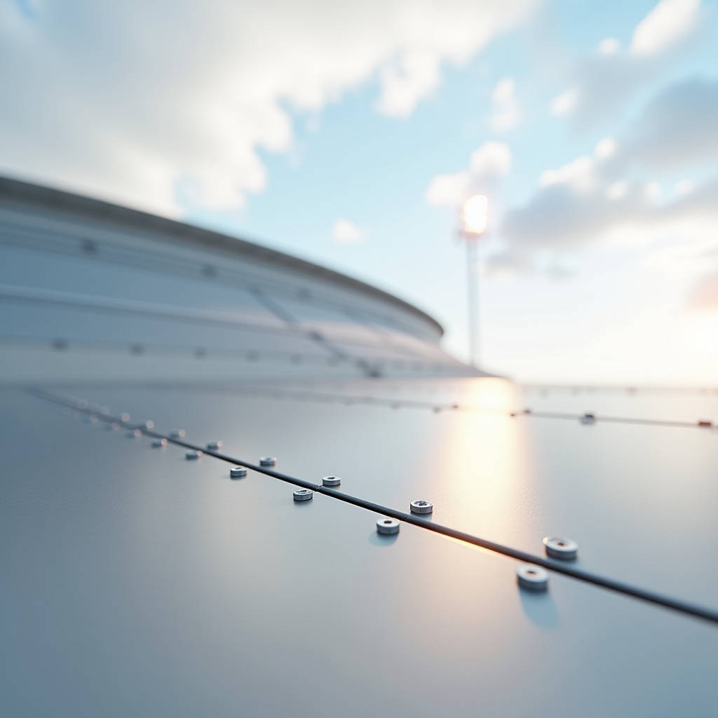
When a stadium facade panel system fails, it rarely fails quietly. The noise travels — a low-frequency rattle across 8,000 square metres of aluminium skin, audible even over 90 decibels of crowd roar. That sound is the result of a single overlooked variable: wind load miscalculation at the fixing point. Most stadium facade panels are specified correctly for material grade, thickness, and coating. Where projects go wrong is the gap between what the panel can withstand and what the substructure actually transmits under dynamic loading. This article examines that gap — the engineering of wind load resistance in stadium facade panels, from calculation methodology through to fixing design, testing protocols, and the cost implications of getting it wrong.
Why Wind Load Calculations Differ for Stadium Facade Panels
Office towers and residential blocks face predictable wind patterns. A rectangular high-rise in a city grid generates a pressure profile that computational fluid dynamics models can map with reasonable accuracy. Stadiums are different. The geometry is rarely orthogonal. Curved bowls, sweeping canopies, open concourses, and sudden transitions between solid and void create pressure differentials that standard building codes struggle to capture.
The governing standard for wind actions on structures, ISO 4354:2009, acknowledges this complexity but leaves the detailed methodology to national annexes. In practice, most stadium projects end up requiring a hybrid approach: baseline wind speeds from the local meteorological record, adjusted for terrain roughness and topography, then refined through wind tunnel testing on a scale model. The panel engineer rarely sees the full wind tunnel report. What arrives at the fabrication stage is a simplified pressure map — often with peak negative pressures at canopy edges and positive pressure bands across the main bowl that are 30-50% higher than the surrounding facade zones.
A stadium facade panel on the upper bowl might need to handle suction pressures of -2.5 kPa while a panel on the same building at ground level sees only -0.8 kPa. Specifying a single panel type across all zones is possible but wasteful. The smarter approach — and the one that procurement teams increasingly demand — is zone-specific panel engineering: thicker material where pressures peak, standard gauge elsewhere, with identical visual appearance across all zones.
Field Note: On a 45,000-seat stadium in Southeast Asia, the original specification called for 3.0mm solid aluminium across all facade zones. Wind tunnel testing revealed that 60% of the panel area could safely use 2.5mm material. The re-engineering saved 18 tonnes of aluminium and roughly $140,000 in material cost — without changing a single visible dimension. The key was having the test data before the panel production drawings were locked.
Understanding the Three Pressure Zones on a Stadium Envelope
Every stadium facade can be divided into three aerodynamic zones, and the distinction matters for panel specification. Zone A covers the main bowl walls — the large, relatively flat expanses where wind flows parallel to the surface. Here, pressures are moderate and the dominant load is positive pressure pushing inward. Zone B includes corners, ridges, and any location where the building geometry forces wind to accelerate around an edge. These areas experience suction pressures that can be double the Zone A values. Zone C is the canopy underside and any deep recesses — areas where wind entering from below creates a lifting effect that tries to peel panels away from the substructure.
The problem is that Zone B and Zone C often coincide with the most architecturally prominent parts of the facade. The main entrance, the VIP drop-off canopy, the sweeping corner that faces the city — these are exactly where wind pressures peak and where visual expectations are highest. A panel that deforms visibly under suction load will be noticed. A panel that rattles will be heard.
For solid aluminium stadium facade panels, the governing failure mode under wind suction is not panel rupture — a 2.5mm or 3.0mm aluminium sheet has enormous tensile capacity. The failure mode is excessive deflection that causes permanent deformation at the fixing points, or deflection large enough to create visible oil-canning across the panel face. AAMA 508-14 provides a deflection limit of L/60 for metal wall panels under design wind load, but for stadium applications where the viewing distance can be 50 metres or more, some architects tighten this to L/90 or even L/120 to eliminate any perceptible waviness under peak gusts.
Fixing Design: The Weak Link in Most Specifications
A stadium facade panel is only as strong as its connection to the building. The panel itself — a 2.5mm or 3.0mm solid aluminium sheet with folded returns and welded corner reinforcement — can typically handle wind pressures well beyond what the fixings can transmit. The bottleneck is almost always at the bracket-to-substructure interface.
There are three common fixing systems for stadium facade panels, and each has a different wind load capacity curve. The first is direct fix with exposed fasteners through the panel face. This is the cheapest option and the worst for wind performance — each fastener creates a stress concentration, and the panel cannot move independently of the substructure. Thermal expansion and contraction (which for aluminium at 23.6 × 10⁻⁶ /°C means roughly 2.4mm of movement per metre over a 50°C temperature swing) will eventually loosen the fasteners. Once loose, wind-induced vibration begins. Once vibration begins, the holes elongate. The panel rattles.
The second system is cassette fixing with concealed clips. The panel hooks onto a rail system, and the clips allow differential movement between panel and substructure. This is the standard for mid-range stadium projects. Wind load capacity depends on clip spacing and clip gauge — typically 1.5mm to 2.0mm stainless steel clips at 400mm to 600mm centres, providing a design resistance of 1.5 to 2.5 kPa per clip pair. The limitation is that clip systems rely on the panel's edge stiffness to distribute load between clips. If the panel is large (over 2.4m in one dimension), the edge deflection between clips can become the governing factor.
The third system — and the one that serious stadium projects increasingly specify for high-wind zones — is a welded stud frame on the panel rear face, connected to the substructure via adjustable brackets. Each stud is welded to the panel through a reinforcing plate, and the bracket allows three-axis adjustment during installation. The load path is direct: wind pressure on the panel face transfers to the studs, through the brackets, into the substructure. With properly designed stud spacing (typically 400mm × 400mm or 600mm × 600mm grids), this system can handle design wind pressures exceeding 4.0 kPa. The cost premium over clip fixing is roughly 25-35%, but for Zone B and Zone C locations, the alternative is a panel that moves in the wind.
Pro Tip: When reviewing fixing shop drawings for stadium facade panels, check the bracket slot length. A slot that allows only 3mm of vertical adjustment will not accommodate the cumulative tolerance stack from the steel substructure. We specify 8mm minimum slots for all stadium projects, and 12mm where the steelwork spans more than 15 metres between expansion joints. The extra slot length costs nothing in fabrication but saves days of site rework.
Material Gauge Selection: Balancing Weight, Cost, and Wind Resistance
Solid aluminium stadium facade panels are typically produced in three gauges: 2.0mm, 2.5mm, and 3.0mm. The choice of gauge affects wind load capacity, but not in a linear way. Doubling the thickness from 2.0mm to 4.0mm would theoretically increase bending stiffness by a factor of eight (stiffness is proportional to thickness cubed). In practice, the useful range for stadium applications is narrower because weight becomes a constraint — a 3.0mm panel weighs roughly 8.1 kg/m² before adding the fixing system, and a large stadium facade might cover 20,000 m² or more. The structural steel supporting that facade was designed for a specific cladding weight, and exceeding it triggers a cascade of redesign costs.
The table below summarises the practical wind load capacity ranges for solid aluminium stadium facade panels at different gauges and fixing configurations, based on a typical panel size of 1200mm × 2400mm with four-edge support.
| Panel Gauge | Fixing Type | Design Wind Load (kPa) | Deflection at Design Load | Weight (kg/m²) | Relative Cost Index |
|---|---|---|---|---|---|
| 2.0mm | Clip fix, 600mm centres | 1.2 | L/55 | 5.4 | 1.00 |
| 2.5mm | Clip fix, 600mm centres | 1.8 | L/70 | 6.75 | 1.18 |
| 2.5mm | Stud frame, 600×600mm | 2.5 | L/90 | 6.75 | 1.35 |
| 3.0mm | Clip fix, 400mm centres | 2.4 | L/85 | 8.1 | 1.40 |
| 3.0mm | Stud frame, 400×400mm | 4.0+ | L/120 | 8.1 | 1.65 |
These values assume PVDF-coated aluminium to AAMA 2605 standards, with aluminium alloy 3003-H14 or 5052-H32. The cost index is relative to the baseline 2.0mm clip-fix system and includes material, fabrication, and fixing components but excludes installation labour and substructure.
The Role of Wind Tunnel Testing in Panel Specification
Building codes provide wind speed maps and pressure coefficients for standard building shapes. A stadium is not a standard building shape. The only reliable way to determine design wind pressures for stadium facade panels is through boundary layer wind tunnel testing on a physical scale model, typically at 1:300 or 1:400 scale, with pressure taps at 200 to 500 locations across the facade surface.
The wind tunnel report will produce pressure coefficient (Cp) values for each tap location, from which the design pressure is calculated using the site-specific design wind speed. What matters for panel engineering is not the mean pressure but the peak pressure — typically the peak 3-second gust pressure at the relevant return period, which for stadium structures is usually 50 years per ASCE 7-22 or 50 years per Eurocode EN 1991-1-4.
A common mistake is to take the peak positive pressure from the wind tunnel report and apply it uniformly across an entire facade zone. The wind tunnel data is point-specific. A pressure tap near the top corner of the stadium bowl might record -3.2 kPa peak suction while a tap 20 metres away on the same elevation records -1.4 kPa. Averaging these values produces a design pressure that is unconservative for the corner and wasteful for the mid-span. The correct approach is to map the pressure contours onto the panel layout drawing and assign each panel a design pressure based on its actual location.
This level of detail requires close coordination between the wind engineering consultant, the facade engineer, and the panel fabricator. On projects where we have been involved early enough to influence this process, the panel specification ends up with two or three distinct fixing configurations rather than a single over-engineered solution. The cost savings come from not putting 3.0mm stud-frame panels where 2.5mm clip-fix panels would do the job.
Thermal Movement and Wind Load: The Combined Effect
Wind load and thermal movement are usually treated as separate design checks. In a stadium facade, they interact. A panel that has expanded under solar heating is pressing against its neighbours or its fixings. When a wind gust hits that same panel, the load path is different from what the isolated wind load calculation assumes.
The coefficient of thermal expansion for aluminium is 23.6 × 10⁻⁶ per °C. A 3-metre-long panel subjected to a 60°C temperature rise (from a winter night low of -5°C to a summer afternoon surface temperature of 55°C, which is conservative but achievable on a dark-coloured PVDF finish) will expand by approximately 4.2mm. If the panel joints are designed for 6mm nominal gap, that expansion consumes 70% of the available movement capacity before any wind load is applied.
When wind suction then pulls the panel outward, the panel edges that were already close to contact now bind against the adjacent panels. The load that was supposed to distribute across all four edges concentrates at the binding points. The fixings at those locations see loads 2-3 times higher than the design value. Over hundreds of load cycles — a single match day with gusty conditions can produce thousands of pressure fluctuations — the fixings fatigue. The first sign is usually a rattle that the stadium operator dismisses as "normal." The second sign is a panel that has shifted visibly out of plane.
The solution is joint width design that accounts for thermal movement, fabrication tolerance, installation tolerance, and wind-induced deflection simultaneously. For a 3-metre panel, the minimum joint width should be 10mm, not the 6mm that many specifications default to. The 4mm difference is invisible from 30 metres away but eliminates the binding problem entirely.
Testing Protocols Beyond the Standard
Standard curtain wall testing per ASTM E283 (air leakage) and ASTM E331 (water penetration) is necessary but not sufficient for stadium facade panels. Two additional tests matter for wind performance.
The first is dynamic wind load testing, sometimes called "wind fatigue testing" or "cyclic pressure testing." A full-scale mockup of the panel system — typically 3 panels wide by 3 panels high, with actual fixings and substructure — is subjected to repeated pressure cycles that simulate the fluctuating wind loads experienced during a storm or a windy match day. The test sequence per AAMA 501.1 involves applying positive and negative pressures at increasing magnitudes, with thousands of cycles at each level. The pass criterion is no permanent deformation, no fastener loosening, and no change in air or water leakage performance after the cycling.
The second is impact resistance testing. Stadium facades at ground level and in concourse areas are vulnerable to impact from crowd movement, maintenance equipment, and occasionally deliberate abuse. A panel that can handle 3.0 kPa of wind pressure might still dent when struck by a heavy object. The relevant standard is ASTM E1886 for impact resistance of exterior wall systems, with the missile type and impact energy specified according to the project's risk assessment. For stadium applications, a 2.5mm or 3.0mm solid aluminium panel with a properly designed rear stiffener frame will typically pass the large missile impact test without difficulty, but the fixing system needs to be checked — an impact load is concentrated and instantaneous, unlike the distributed sustained load of wind pressure.
Procurement Implications: What the Specifier Needs to Know
Wind load engineering for stadium facade panels is not a line item that appears on a typical bill of quantities. It is embedded in the panel design, the fixing design, and the testing regime. When procurement teams compare bids from different panel fabricators, the unit price per square metre tells only a fraction of the story.
A fabricator quoting 2.5mm clip-fix panels at $X per m² might be cheaper than one quoting 3.0mm stud-frame panels at $X+30% per m². But if the cheaper system requires a heavier steel substructure to limit deflection, or if it needs more expansion joints, or if the wind tunnel data shows that 40% of the facade area actually needs the heavier system anyway, the total installed cost may favour the apparently more expensive option.
The procurement strategy that works for stadium projects is to separate the panel supply contract from the preliminary wind engineering. Engage a wind consultant early, get the pressure map, and then issue a performance specification that states the required design pressure for each facade zone. Let fabricators propose their own solutions — panel gauge, fixing type, stiffener layout — to meet those pressures. The bids become technically comparable because they are all responding to the same performance criteria, not the same prescriptive specification.
Suppliers like Futeng® with experience in stadium projects across multiple climate zones can provide valuable input during this value-engineering phase, particularly on the interaction between panel gauge, stiffener design, and fixing layout. The right conversation at the right time — before the shop drawings are approved — can save six figures on a large stadium facade package.
Summary: Engineering Stadium Facade Panels for Wind Load
Wind load is the dominant structural load on stadium facade panels, and it behaves differently on stadium geometries than on conventional buildings. The key engineering decisions — panel gauge, fixing type, stiffener layout, joint width — all flow from a proper understanding of the wind pressure distribution across the specific stadium form. Wind tunnel testing is not optional for major stadium projects. The data it provides should drive zone-specific panel specifications rather than a single over-engineered solution applied uniformly. Fixing design deserves as much attention as panel design, because the fixing is the load path bottleneck. Thermal movement must be considered together with wind load, not as a separate check. And the procurement process should be structured around performance criteria rather than prescriptive specifications, to allow fabricators to propose the most cost-effective solution that meets the required wind load performance for each facade zone.