Commercial Building Cladding Joint Design That Keeps Water Out for Decades
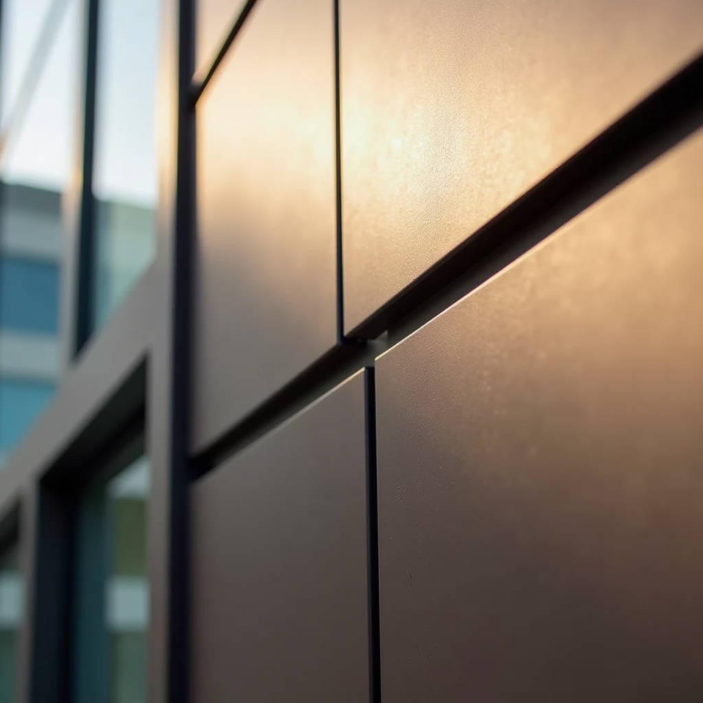
When a commercial building cladding system fails, the root cause rarely traces back to the panel itself. More often, the problem starts at the joint. A sealant bead that cured too fast in low humidity. A gasket compressed beyond its service limit. A drainage channel blocked by construction debris that nobody cleared before handover. These are the details that separate a facade that performs for 30 years from one that leaks in three. This article examines the engineering logic behind weathertight joints in solid aluminium cladding systems, the specific failure mechanisms that recur across projects, and the practical decisions that determine whether a commercial building cladding installation stays dry through decades of thermal cycling, wind-driven rain, and building movement.
Why Joints Dictate the Fate of Commercial Building Cladding
A solid aluminium panel, whether 2.5mm or 3.0mm thick with a PVDF-coated surface, is inherently impermeable. Water does not pass through the metal. The vulnerability lies entirely in the gaps between panels. A typical commercial facade might contain 8,000 to 15,000 linear metres of jointing. Each metre represents a potential entry point for water, a thermal bridge, and a location where differential movement must be accommodated.
The physics is straightforward but unforgiving. A 3-metre aluminium panel subjected to a 60°C surface temperature swing will expand and contract by approximately 4.2mm over its length. Multiply that across a 40-metre elevation and the cumulative movement reaches 56mm. If the joint design does not absorb this movement independently at each panel edge, stress concentrates at fixed points. Sealant tears. Gaskets extrude. Water finds the path of least resistance.
Wind-driven rain compounds the problem. At 75 km/h wind speeds, water droplets strike the facade with enough kinetic energy to travel upward against gravity. A 1mm gap under negative pressure of 600 Pa can draw water 40mm into the cavity. This is not theoretical. The ASTM E1105 water penetration test simulates exactly these conditions, and many joint configurations fail at pressures well below the specified 20% of design wind load.
Sealant Joints: The Traditional Approach and Its Hidden Demands
Butt-joint sealant systems remain the most common approach for commercial building cladding because they are cost-effective and familiar to installation crews. The principle is simple: a backing rod sets the joint depth, and a high-performance sealant fills the gap. The execution is where things unravel.
Joint Dimensioning That Actually Works
The width-to-depth ratio is the single most critical parameter. Industry guidance from sealant manufacturers and the ASTM C1193 standard calls for a 2:1 width-to-depth ratio for joints up to 12mm wide. For joints between 12mm and 25mm, the depth should not exceed 12mm. Wider joints need depth capped at approximately half the width. Get this wrong and the sealant cannot stretch without cohesive failure.
Consider a 15mm joint between two solid aluminium panels. The correct depth is 8-10mm. On site, an installer might push the backing rod too deep, creating a 15mm-deep sealant bead. The movement capability drops from ±25% to perhaps ±12%. A panel that needs to accommodate 4mm of movement in a 15mm joint requires 27% movement capability. The joint fails within the first seasonal cycle.
| Joint Width (mm) | Recommended Depth (mm) | Maximum Movement Capability (±%) | Common Site Error |
|---|---|---|---|
| 10 | 5-6 | 25 | Backing rod pushed too deep |
| 15 | 8-10 | 25 | Depth exceeds 12mm |
| 20 | 10 | 25 | No backing rod used |
| 25 | 12 | 20 | Three-sided adhesion |
| 30 | 12-15 | 15 | Insufficient tooling |
Adhesion Failure: The Substrate Preparation Problem
PVDF coatings based on Kynar 500 resin systems are engineered for chemical inertness. That is precisely what makes them excellent at resisting acid rain and UV degradation, and precisely what makes them difficult to bond to. A sealant applied directly to an untreated PVDF surface will eventually peel away, regardless of the sealant quality.
The solution is a two-step process that many specifications gloss over. First, the PVDF surface must be mechanically abraded along the bond line using a Scotch-Brite pad or fine-grit sandpaper. This removes the surface gloss and creates micro-roughness. Second, a compatible primer specified by the sealant manufacturer must be applied within the open time window. Skipping either step produces a joint that looks correct on day one but has no long-term adhesion.
Field Note: On a 12-storey commercial project in Kuala Lumpur, we traced 23 separate leaks to sealant adhesion failure across PVDF-coated panels. Every single failure site showed the same pattern: the primer was applied, but the abrasion step was skipped. The sealant peeled away from the coating in a clean sheet. The repair cost exceeded the original jointing budget by 40%. Always verify the abrasion step with a simple tape-peel adhesion test per ASTM C1521 before allowing full production.
Gasket Systems: Mechanical Sealing for Higher Performance
EPDM gasket systems offer a fundamentally different approach. Instead of relying on chemical adhesion, they use mechanical compression to create a weather seal. A properly designed gasket joint in a commercial building cladding system can accommodate significantly more movement than sealant, typically ±35% to ±50% of the joint width, and the performance does not degrade with UV exposure the way organic sealants do.
Compression Set and Long-Term Recovery
The critical material property is compression set, measured per ASTM D395 Method B. A high-quality EPDM gasket formulated for architectural applications should exhibit compression set below 25% after 22 hours at 70°C. Lower-grade compounds might test at 40-50%. The difference manifests years later. A gasket with 25% compression set retains 75% of its original sealing force after decades of compression. A gasket with 50% compression set loses half its sealing force, and water penetrates at lower pressures.
Temperature matters too. EPDM performs reliably from -50°C to +130°C. Silicone gaskets extend the upper range to 200°C but cost 3-4 times more and have lower tear strength. For standard commercial building cladding applications outside of industrial high-heat zones, EPDM remains the practical choice.
The Two-Stage Drainage Principle
The most robust gasket-jointed commercial building cladding systems employ a two-stage seal: an outer gasket that deflects the majority of wind-driven rain, and an inner gasket that acts as the primary air seal. Between them, a drained and ventilated cavity allows any water that penetrates the outer seal to drain downward and exit through weep holes at each floor level.
This pressure-equalised design reduces the pressure differential across the outer gasket. When the cavity pressure approaches the external wind pressure, the driving force for water penetration drops to near zero. The inner gasket then only needs to handle air infiltration, which it does at much lower pressure differentials. The system works, but it requires meticulous detailing at horizontal joints, corners, and window interfaces. A single missing end dam can short-circuit the entire pressure equalisation for that cavity zone.
Thermal Movement: Engineering the Gaps
Solid aluminium has a coefficient of thermal expansion of approximately 23.6 × 10⁻⁶ per °C. A 3-metre panel on a dark-coloured facade in Dubai might see a surface temperature swing from 15°C at night to 85°C under direct afternoon sun. That is a 70°C delta, producing 4.96mm of movement per panel.
The joint width must be calculated for the specific project location, panel colour, and orientation. Light-coloured panels in temperate climates might need 8mm joints. Dark panels in hot climates might need 16mm or more. The calculation is straightforward but frequently ignored in favour of a standard 10mm or 12mm joint that looks visually consistent but may be structurally inadequate.
Fixing methods interact with thermal movement in ways that are not always obvious. A panel fixed with four bolts near the corners has less freedom to expand than a panel hung on a rail system with slotted connections. The joint width must increase if the fixing method restricts movement. Conversely, a properly detailed rail-hung system with elongated holes can accommodate movement within the fixing itself, reducing the demand on the joint seal.
Installation Sequence: The Order That Determines Performance
Joint performance depends heavily on the order in which panels are installed. The sequence must account for cumulative tolerances. If panels are installed from left to right without periodic checks, a 1mm accumulated error per panel across 40 panels produces a 40mm misalignment at the far end. The joints at that end will be either too tight or too wide, and neither condition performs as designed.
The correct approach establishes control lines at regular intervals, typically every 5 to 8 panels, and installs from both sides toward the control line. This halves the accumulated tolerance and keeps all joints within the designed width range. Laser measurement at each control line verifies the position before proceeding.
Pro Tip: On a recent 28,000m² commercial building cladding project, we introduced a mandatory joint-width check at every 6th panel using a simple go/no-go gauge. Joints outside the specified width tolerance of ±2mm triggered an immediate stop and correction. This added approximately 15 minutes per floor level to the installation schedule but eliminated the end-of-facade joint-width drift that had caused rework on previous projects. The total time saved in rework avoidance was estimated at 120 man-hours.
Interface Detailing: Where Most Specifications Fall Short
The joint between two identical panels on a flat elevation is the easy case. The real challenges occur at interfaces: panel-to-window, panel-to-louvre, panel-to-parapet, and panel-to-soffit. These transitions involve different materials with different expansion coefficients, different fixing methods, and different water management strategies.
A solid aluminium panel at 23.6 × 10⁻⁶ per °C meets an aluminium window frame at the same coefficient. That is manageable. The same panel meeting a steel louvre at 12.0 × 10⁻⁶ per °C introduces differential movement that the joint seal must absorb. The sealant or gasket must be selected for the combined movement of both substrates, not just the panel movement.
At the parapet, the joint must also handle the transition from vertical cladding to horizontal capping. Water running down the facade hits the parapet and can be driven upward by wind turbulence at the roof edge. The detailing here needs a positive drip edge, a continuous flashing that extends behind the cladding, and a seal that works under both positive and negative pressure. A simple sealant bead at the parapet-cap junction is not enough.
Quality Verification: Testing Beyond the Mock-Up
A single laboratory mock-up test per ASTM E283 and ASTM E1105 provides confidence in the design. It does not provide confidence in the installation. Site testing is the only way to verify that the joints actually installed on the building perform as well as the joints built in the laboratory.
Spray-rack testing per AAMA 501.2 should be conducted on at least 5% of the installed area, with a focus on interface details and areas where the installation sequence might have introduced tolerance issues. The test applies water at 3.4 litres per minute per square metre at a specified air pressure differential, and the interior is inspected for leakage. Failed areas are marked, repaired, and retested.
This is not cheap. A comprehensive site-testing programme on a large commercial building cladding project might cost $15,000 to $30,000. But it is cheaper than the alternative. Water ingress discovered after fit-out leads to interior damage, mould remediation, business interruption, and legal claims that routinely exceed six figures.
Material Selection for Joint Components
The panels themselves are typically 2.0mm, 2.5mm, or 3.0mm solid aluminium, with 3.0mm being the standard for commercial building cladding where wind loads and span distances demand higher stiffness. The PVDF coating system, applied at a minimum dry film thickness of 30-35 microns per AAMA 2605, provides the weather barrier on the visible face. But the joint components need equal attention.
Backing rods should be closed-cell polyethylene foam with a skin that prevents sealant adhesion to the rod itself. This ensures the sealant bonds only to the two panel edges, creating the ideal hourglass cross-section that can stretch and compress without constraint. Open-cell rods or rods without a skin allow three-sided adhesion, which reduces the effective movement capability by more than half.
Fasteners in the joint zone, where used, must be stainless steel, grade 316 for coastal or industrial environments. Grade 304 fasteners will eventually corrode in the presence of chlorides, and the corrosion products can stain the PVDF surface. The cost difference between 304 and 316 is approximately 20-30%, which is negligible compared to the cost of replacing stained panels on a completed facade.
For projects specifying high-performance joint systems, suppliers like Futeng® provide solid aluminium cladding panels with factory-machined edge details that accept specific gasket profiles. This shifts the tolerance risk from the site to the factory, where CNC machining ensures consistent joint dimensions that site cutting cannot match.
Making the Right Joint Decisions
There is no universally correct joint system for commercial building cladding. The choice depends on the project's specific conditions: design wind pressure, exposure category, annual rainfall, temperature range, building height, panel size, and the architect's aesthetic requirements for joint visibility.
Sealant joints make sense for low to mid-rise buildings in moderate climates where the joint width can be kept to 10-15mm and the movement demand is within the sealant's capability. They are cost-effective, the materials are widely available, and skilled applicators are easy to find. The risk lies in substrate preparation and quality control, not in the system itself.
Gasket systems justify their higher material cost on high-rise buildings, buildings in extreme climates, and projects where the facade must perform for 50 years or more with minimal maintenance. The mechanical seal does not degrade the way organic sealants do, and the drained-and-ventilated cavity provides a second line of defence. The risk shifts to the accuracy of the supporting framework and the precision of panel fabrication.
Whichever system is chosen, the specification must be detailed. It must state the joint width and depth, the backing rod material and size, the primer type and application method, the sealant or gasket material and grade, the surface preparation requirements, the installation tolerances, and the site testing protocol. A specification that says "seal all joints with silicone sealant" is not a specification. It is a warranty claim waiting to happen.
The joint is the smallest component of a commercial building cladding system by volume, but it carries the largest share of the performance burden. Get it right, and the panels will look the same in year 20 as they did on day one. Get it wrong, and the most expensive PVDF coating in the world will not keep the building dry.