Luxury Aluminum Cladding Flatness and Thermal Engineering for High Rise Facades
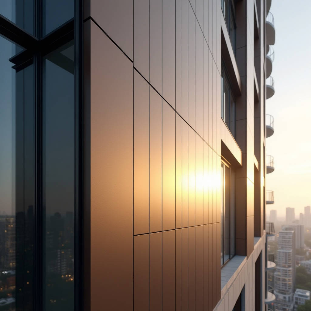
When a project brief calls for a facade that reads as bespoke, monolithic, and physically substantial, the specification almost always lands on solid aluminium panels. Not composite. Not thin-gauge sheet. The distinction matters because the engineering logic behind luxury aluminum cladding has less to do with surface appearance and more to do with how a 2.5 mm or 3.0 mm solid sheet behaves across a 30-year lifecycle. Architects chasing shadow-gap precision and general contractors managing installation tolerances on high-rise curtain walls both converge on the same question: how do you keep a large-format aluminium panel dead flat under thermal cycling, wind suction, and the accumulated stress of its own self-weight? This article examines that specific structural problem — the interplay between panel thickness, stiffener layout, and thermal expansion — and maps out the fabrication and installation decisions that separate a facade that stays optically true from one that telegraphs every internal rib through the finished surface.
Why Flatness Fails on Luxury Facades
Visual flatness on a solid aluminium rainscreen is not a cosmetic preference. It is a structural performance metric. When a 3.0 mm thick panel spans 1,200 mm between attachment points, the unsupported zone experiences a complex stress state: dead load pulling downward, negative wind pressure pulling outward, and solar radiation driving thermal expansion at roughly 0.024 mm per linear meter per degree Celsius. A 4-meter panel subjected to a 60°C temperature swing from night to midday sun will try to grow by nearly 5.8 mm. If the attachment system restrains that movement, the panel buckles. If the stiffener grid is too sparse, the panel oil-cans — a phenomenon where the surface pops in and out under light pressure, visible as rippling distortion under oblique lighting.
Oil-canning is the single most common rejection reason on luxury aluminum cladding packages. The AAMA 508 and 509 standards provide testing protocols for pressure-equalized rainscreen systems, but they do not prescribe a specific stiffener layout. That responsibility falls on the fabricator's engineering team. The calculation starts with the panel's aspect ratio and thickness. A 2.5 mm panel at 1,000 mm x 3,000 mm will exhibit more deflection under identical wind load than a 3.0 mm panel at 800 mm x 2,400 mm. But thickness alone is not the answer — adding 0.5 mm of material increases weight by roughly 1.35 kg/m², which cascades into heavier substructure, larger brackets, and more demanding dead-load anchors.
Field Note: On a 28-story curtain wall project in Singapore, we rejected 40% of the first batch of 3.0 mm panels because stiffener weld marks telegraphed through the PVDF finish. The root cause was not welding heat — it was the stiffener profile. The fabricator used 25 mm x 25 mm x 3 mm aluminium angles with a continuous fillet weld. Switching to 40 mm x 20 mm hat-section stiffeners with intermittent 40 mm stitch welds at 200 mm centers eliminated the problem. The wider flange distributed local stress and the stitch pattern reduced total heat input by roughly 60%. Panel flatness after installation measured within 2 mm over a 3-meter diagonal — well inside the 0.5% tolerance specified in the contract.
Stiffener Design: The Hidden Engineering Layer
Stiffeners on solid aluminium panels serve two functions that are often conflated. The primary function is to increase the section modulus of the panel assembly, reducing deflection under wind load. The secondary function — and the one that matters more for luxury aluminum cladding — is to break the panel surface into smaller, restrained sub-panels that resist thermal buckling. The difference between a well-stiffened panel and a poorly stiffened one becomes visible at around 40°C surface temperature differential, which is routine on dark-colored facades in Middle Eastern or Southeast Asian climates.
The most common stiffener material is extruded aluminium angle or hat section, grade 6063-T5 or 6063-T6, attached to the panel back face using either MIG welding or structural adhesive. Welding introduces a heat-affected zone that locally anneals the panel material, reducing yield strength in the immediate vicinity of the weld. For 5052-H32 aluminium sheet — the workhorse alloy for solid cladding panels — the as-welded yield strength drops from approximately 193 MPa to roughly 90 MPa in the HAZ. This is why some fabricators prefer structural adhesive bonding using two-part epoxy or polyurethane adhesives. Adhesive bonding eliminates the HAZ entirely and distributes stress over a continuous bond line rather than discrete weld points.
The trade-off is durability. Adhesive bonds degrade under sustained shear stress and moisture exposure. A 2018 study published by the ASTM International showed that polyurethane adhesives on aluminium substrates retained approximately 70% of their initial lap shear strength after 5,000 hours of accelerated weathering per ASTM G154 Cycle 1. Welded stiffeners, by contrast, have no degradation mechanism other than corrosion at the weld interface — which is managed through proper pretreatment and coating.
| Stiffener Attachment Method | Bond Strength (MPa) | HAZ Impact | Long-Term Durability | Cost Index (Relative) |
|---|---|---|---|---|
| Continuous MIG Weld | 90-110 (as-welded) | Significant — annealed zone | Excellent if pretreated | 1.0 (baseline) |
| Intermittent Stitch Weld | 90-110 (localized) | Moderate — reduced total heat | Excellent if pretreated | 0.85 |
| 2-Part Epoxy Adhesive | 15-25 (lap shear) | None | Good — UV-stable variants | 1.20 |
| Polyurethane Adhesive | 8-18 (lap shear) | None | Moderate — moisture-sensitive | 1.10 |
| Mechanical Fastening (Rivets) | Varies by fastener | None | Good — galvanic risk | 0.75 |
Thermal Movement: The Numbers That Drive Joint Design
Solid aluminium expands and contracts. Every millimeter of that movement must be accommodated somewhere in the system. The coefficient of linear thermal expansion for 5052 aluminium is 23.8 x 10⁻⁶ per °C. For a 4,200 mm tall panel installed at 25°C and exposed to a surface temperature range of -10°C to +80°C (dark bronze PVDF in a desert climate), the total movement is:
ΔL = 23.8 × 10⁻⁶ × 4,200 × 90 = 8.99 mm
That is nearly 9 mm of growth and contraction that the joint design must absorb without crushing sealant, deforming the panel edge, or transmitting load to adjacent panels. The standard approach on luxury aluminum cladding systems is to use a combination of fixed points and sliding points. Each panel typically has one fixed anchor — usually near the geometric center or at the top edge — and all other attachment points are slotted to permit movement in the primary expansion direction.
The slot length calculation is straightforward but frequently underspecified. A slot must accommodate the full movement range plus a safety factor of 1.5, plus the installation tolerance of the substructure. On a curtain wall with vertical aluminium mullions installed to a tolerance of ±3 mm over 4 meters, the slot length at the bottom of a 4.2-meter panel should be at minimum:
Slot = (8.99 × 1.5) + 3 = 16.5 mm of total travel
This means a slot length of approximately 20 mm to allow for the fastener shank diameter. Specifying a 12 mm slot on a large dark-colored panel is a guaranteed path to field buckling, and the problem will not appear until the first hot season after handover — precisely when the client's facility management team is most sensitive to facade defects.
Pro Tip: When reviewing shop drawings, check the slot orientation relative to the panel's long axis. On a panel that is 1,200 mm wide and 4,000 mm tall, the dominant expansion is vertical. The top attachment should be fixed (or slotted horizontally only), and the bottom attachment should be slotted vertically. Mid-span attachments, if used, should be slotted in both directions. A common error is to slot all attachments identically, which creates an under-constrained panel that rattles under wind buffeting.
Coating Systems and Their Effect on Thermal Behavior
The coating on a solid aluminium panel does more than provide color. It directly affects the panel's surface temperature, which drives thermal movement. A white PVDF coating with a Total Solar Reflectance (TSR) of 0.70 will keep the panel surface roughly 15-20°C cooler than a dark bronze coating with a TSR of 0.25 under identical solar irradiance. This temperature difference translates directly into reduced thermal movement and lower stress on the stiffener bonds.
PVDF coatings based on Kynar 500 resin — the industry benchmark for luxury aluminum cladding — are applied as a multi-coat system: a chrome-based conversion coating or non-chrome pretreatment, a primer layer at 5-8 microns, a color coat at 25-30 microns, and a clear topcoat at 12-15 microns. Total Dry Film Thickness (DFT) runs 40-55 microns. The clear coat is not optional for exterior applications; it contains the UV-stabilizing package that prevents chalking and color fade. Per AAMA 2605, the highest performance specification for architectural coatings on aluminium, a compliant PVDF system must demonstrate less than 5 Delta E color change and less than 8 gloss unit reduction after 10 years of South Florida exposure at 45° tilt.
Some fabricators offer FEVE (fluoroethylene vinyl ether) coatings as an alternative to PVDF. FEVE systems can achieve higher gloss levels — up to 90 GU at 60° — compared to PVDF's practical limit of around 40-50 GU. The trade-off is that FEVE coatings are generally thinner, with a typical DFT of 30-40 microns, and have a shorter track record in architectural applications. For projects where the specification explicitly requires AAMA 2605 compliance, PVDF remains the default choice. Futeng® has supplied PVDF-coated solid aluminium panels to projects across Southeast Asia and the Middle East where the coating specification was non-negotiable, and the quality control documentation — including batch-level Delta E measurements and gloss readings — formed part of the material submittal package.
Substructure Interaction: Why the Panel Is Only Half the System
A perfectly flat panel installed on an out-of-tolerance substructure will not look flat. The substructure — typically aluminium T-profiles, hat channels, or steel Z-girts — defines the reference plane to which the panel attaches. On a rainscreen facade, the substructure is installed onto the building's structural wall or slab edge, and any deviation in that substrate propagates through to the finished surface.
The allowable substructure tolerance for luxury aluminum cladding should be specified as ±2 mm over a 2-meter straight edge, measured in both vertical and horizontal directions. This is tighter than the ±5 mm typically allowed for structural steelwork per AISC 303, and it means the substructure installer needs to use adjustable brackets with shimming capability. Fixed brackets that cannot be adjusted in the field are a liability — the only way to correct alignment errors is to dismantle and re-install, which is rarely practical on a construction schedule.
The bracket material also matters. Stainless steel brackets (grade 304 or 316) are preferred for their corrosion resistance and thermal compatibility with aluminium. Carbon steel brackets, even hot-dip galvanized, introduce a galvanic corrosion risk at the steel-aluminium interface. The standard mitigation is a nylon or EPDM isolation pad, but these pads add thickness that must be accounted for in the panel joint dimension. A 1.5 mm isolation pad on each bracket can shift the panel plane by 3 mm, which is enough to create a visible step at panel joints if not compensated in the system design.
Wind Load Performance and Panel Sizing Limits
Wind load governs panel sizing on high-rise facades. The design wind pressure is derived from the project-specific wind speed map per ASCE 7, adjusted for building height, exposure category, and local topography. For a 100-meter-tall building in Exposure Category B (urban/suburban), the design wind pressure at the corner zones can exceed 2.5 kPa. A 1,200 mm x 3,000 mm panel with 3.0 mm thickness and stiffeners at 600 mm centers will typically deflect less than L/180 under this load, which is the common deflection limit for rainscreen panels.
But deflection is not the only criterion. The panel's attachment clips must resist the full wind load in tension (for negative pressure) and compression (for positive pressure), with a safety factor of 3.0 per AAMA 508. A clip designed for a 1.0 kN load with a 3.0 safety factor must have an ultimate capacity of 3.0 kN. This is verified through pull-out testing on the actual substrate — the clip manufacturer's published values are based on ideal conditions and should be derated by 20-30% for field conditions unless project-specific testing is performed.
The interaction between wind load and thermal movement creates a particularly challenging condition at building corners. Corner panels experience the highest wind pressures and the most complex thermal gradients — one edge may be in full sun while the adjacent edge is shaded. The stiffener layout on corner panels should be designed for the worst-case combination of wind suction and thermal stress, which often means reducing the stiffener spacing by 20-25% compared to field-zone panels of the same dimensions.
Fabrication Tolerances That Matter
Panel dimensional tolerances are specified in the project documentation, but the numbers that actually affect installation fit-up are often tighter than the nominal values. A panel that is 1.5 mm over nominal width may not seem problematic — until you realize that 20 panels across a 24-meter facade accumulate 30 mm of extra width, which must be absorbed somewhere. The standard fabrication tolerance for solid aluminium panels is ±1.0 mm on length and width, ±0.5 mm on diagonal difference (squareness), and ±0.3 mm on fold-line straightness.
Fold-line straightness is particularly important for luxury aluminum cladding panels with return edges. A return edge that bows inward or outward by even 0.5 mm creates a visible gap variation at the panel joint. The gap between adjacent panels is typically 15-20 mm on a rainscreen facade, and the human eye can detect a gap variation of 2 mm or more under favorable lighting. This means the combined tolerance of two adjacent panel edges and the installation alignment must stay within roughly 1.5 mm to maintain consistent joint width — a demanding standard that requires disciplined quality control at the fabrication stage.
Futeng® operates a quality control protocol where each panel is measured on a granite inspection table with calibrated digital instruments, and the measurement data is recorded against the panel's unique ID number. This traceability allows the site team to cross-reference any fit-up issue against the fabrication records, distinguishing between a manufacturing defect and an installation error — a distinction that has significant commercial implications in a claims scenario.
Packaging, Logistics, and Site Handling
A panel that leaves the factory flat can arrive on site with a 5 mm bow if the packaging is inadequate. Solid aluminium panels are heavy — a 3.0 mm panel weighs approximately 8.1 kg/m², and a crate containing 20 panels of 1.2 m x 3.0 m weighs over 580 kg. The panels must be packed vertically on A-frame stillages with foam or felt separators between each panel face. Horizontal stacking is a common error that places the full weight of the stack on the bottom panel's stiffeners, which can permanently deform the stiffener bond and create a sag that is visible after installation.
For ocean freight shipments, the crates should be lined with VCI (Volatile Corrosion Inhibitor) paper or film to prevent salt-spray corrosion during transit. The crates themselves should be constructed from plywood with a minimum thickness of 12 mm, reinforced with steel banding, and clearly labeled with the project name, panel ID range, and handling instructions. A crate that collapses during unloading is not just a material loss — it is a schedule impact that can delay facade completion by weeks if replacement panels must be fabricated and shipped.
On site, panels should be stored under cover, away from direct sunlight and standing water. If outdoor storage is unavoidable, the crates should be elevated on timber bearers and covered with breathable tarpaulins — never plastic sheeting, which traps condensation and accelerates corrosion. Each panel should be inspected upon uncrating and any damage documented immediately with photographs and a written report. The window for filing a shipping damage claim is typically 7-14 days after delivery, and missing that window means the cost of replacement falls on the contractor.
Specifying Luxury Aluminum Cladding for Long-Term Performance
The specification for luxury aluminum cladding should address not just the panel itself but the complete system: panel material and thickness, stiffener design and attachment method, coating type and performance standard, attachment system and thermal movement accommodation, substructure tolerance, and quality control documentation. A specification that says "3.0 mm aluminium panel with PVDF coating" is incomplete — it leaves too many decisions to the fabricator's discretion, and those decisions will be driven by cost rather than performance.
A robust specification references specific standards: ASTM B209 for aluminium sheet, AAMA 2605 for PVDF coating performance, AAMA 508 for pressure-equalized rainscreen testing, and ASCE 7 for wind load determination. It defines the allowable deflection limit (typically L/180 for the panel and L/360 for the supporting substructure), the required stiffener spacing, and the acceptable flatness tolerance after installation. It also requires the fabricator to submit engineering calculations stamped by a licensed structural engineer, demonstrating that the panel and attachment system meet the specified performance criteria under the project-specific design loads.
The commercial reality is that a well-specified luxury aluminum cladding system costs more upfront — the material is heavier, the fabrication is more labor-intensive, the quality control is more rigorous, and the packaging is more substantial. But the cost of a facade failure — oil-canning, coating delamination, wind damage, or water ingress — dwarfs the initial premium. A recladding project on an occupied building can cost 3-5 times the original facade budget when you factor in access, logistics, tenant disruption, and reputational damage. The engineering decisions made during specification and shop drawing review are the cheapest insurance against that outcome.