How Joint Design and Drainage Engineering Make Weatherproof Aluminum Panels Perform for Decades
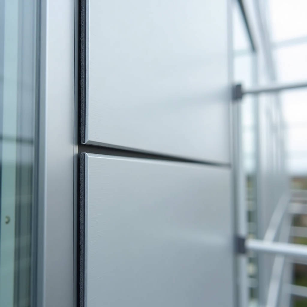
When a curtain wall contractor in Hamburg faces 120 km/h North Sea winds and driving rain, the conversation shifts from aesthetics to survival. Weatherproof aluminum panels are not just a specification line item — they are the primary defense layer between a building's structural skeleton and decades of environmental assault. This article focuses on the joint design and drainage engineering that determine whether a solid aluminum rainscreen system performs for 30 years or starts leaking in three. Too many project teams obsess over panel flatness and PVDF gloss levels while overlooking the gasket geometry, pressure-equalization logic, and thermal movement accommodation that actually keep water out. We will walk through the technical anatomy of weatherproof aluminum panels from the joint outward, examining how extrusion profiles, EPDM gasket selection, and cavity drainage calculations interact under real-world cyclic wind loading.
The Joint Is the System: Why Panel-to-Panel Interfaces Define Weatherproofing
A solid aluminum panel itself is inherently waterproof. A 2.5 mm or 3.0 mm thick 5052-H32 or 3003-H14 aluminum sheet with a properly cured PVDF coating will not allow moisture penetration through the material. The vulnerability lies entirely in the joints — the vertical and horizontal gaps between adjacent panels where wind-driven rain, capillary action, and pressure differentials conspire to move water inward. In a typical rainscreen facade, joints account for perhaps 3% to 5% of the total surface area but are responsible for 100% of potential water ingress failures.
The industry standard for open-joint rainscreen systems, as defined by AAMA 508-14 and related testing protocols, requires that the joint design accommodate three simultaneous physical phenomena: thermal expansion and contraction of the aluminum panels, differential movement between the cladding and the structural backup wall, and the dynamic pressure fluctuations caused by wind gusts. A 3-meter-long aluminum panel will expand by approximately 6.5 mm across a 70°C temperature swing. If the joint is too narrow, panels buckle. If the joint is too wide, wind-driven rain penetrates the cavity unchecked. The sweet spot for most commercial projects using weatherproof aluminum panels falls between 8 mm and 15 mm, but this number must be validated against the specific project's wind load data and the panel's alloy grade.
Field Note: On a coastal project in Southeast Asia, we observed that 10 mm open joints specified on the drawings were being installed at 6 mm to 8 mm by crews unfamiliar with thermal movement requirements. Within six months, panel edges showed visible deformation at mid-span. The fix required removing and re-fabricating 40% of the panels. Always verify joint widths during the first 50 m² of installation — not at the punch list stage.
Pressure-Equalized vs. Drained-and-Vented: Choosing the Right Rain Screen Logic
The term "rainscreen" gets thrown around loosely, but the engineering distinction between a pressure-equalized (PE) system and a drained-and-vented (DV) system has major implications for weatherproof aluminum panels. A true pressure-equalized rainscreen divides the cavity behind the panels into sealed compartments, typically using vertical baffles at each floor level and horizontal compartment seals at structural columns. The goal is to allow the air pressure in the cavity to equalize with the external wind pressure almost instantaneously, neutralizing the pressure differential that drives water through the joints.
A drained-and-vented system, by contrast, does not attempt full compartmentalization. It relies on gravity drainage and a continuous air gap behind the panels, accepting that some water will enter the cavity and must be managed through weep holes, flashing, and a robust drainage plane on the backup wall. The PE approach is technically superior but demands far more coordination between the aluminum panel fabricator, the support framing installer, and the air/water barrier contractor. The DV approach is simpler to execute and often adequate for low-rise buildings in moderate climates.
The selection matrix for weatherproof aluminum panels should consider building height, local wind climate, and the consequence of water ingress. For a hospital or data center, the incremental cost of a PE system — roughly 12% to 18% more than DV — is trivial compared to the cost of interior water damage. For a warehouse or parking structure, a well-detailed DV system with properly lapped flashings will perform adequately.
EPDM Gaskets and Silicone Sealants: The Unsung Heroes of Weatherproofing
Behind every weatherproof aluminum panel joint that performs for decades, there is either a high-quality EPDM gasket or a properly specified structural silicone sealant. These materials absorb the movement, bridge the gap, and resist UV degradation, ozone attack, and compression set. EPDM (ethylene propylene diene monomer) gaskets are the dominant choice for open-joint systems because they maintain elasticity across a temperature range from -50°C to +150°C and resist compression set better than neoprene or PVC alternatives. The Shore A hardness specification matters: 60 to 70 durometer is typical for vertical joints, while horizontal joints that carry more gravity load may require 70 to 75 durometer.
Silicone sealants enter the picture when the joint must be fully sealed — for example, in a barrier wall system or at transitions around windows and louvers. The key specification here is movement capability, expressed as a percentage of the joint width. A Class 50 silicone (per ASTM C920) can accommodate ±50% joint movement, meaning a 10 mm joint can stretch to 15 mm or compress to 5 mm without losing adhesion. For weatherproof aluminum panels on high-rise facades subject to significant inter-story drift, Class 50 is the minimum acceptable grade. Class 25 silicones have no place in exterior cladding joints, regardless of cost savings.
Pro Tip: When specifying silicone sealant for aluminum panel joints, always require the sealant manufacturer to provide an adhesion test report on the specific PVDF coating system being used. Not all PVDF formulations bond equally well to all silicones. We have seen adhesion failures on Kynar 500-based coatings when paired with neutral-cure silicones that lacked a primer step. The test takes 48 hours and costs almost nothing compared to a resealing campaign.
Coating Systems and Their Role in Long-Term Weather Resistance
While the joints handle water management, the coating system on weatherproof aluminum panels handles everything else: UV radiation, salt spray, acid rain, and industrial pollutants. The industry benchmark is a three-coat PVDF system based on Kynar 500 or Hylar 5000 resin, with a minimum total dry film thickness of 30 to 35 microns. The three-coat structure consists of a corrosion-resistant primer (typically 5 to 8 microns), a color coat containing the PVDF resin and pigments (20 to 25 microns), and a clear topcoat that provides gloss control and additional UV shielding (5 to 8 microns).
Two-coat PVDF systems, at 25 to 28 microns total DFT, are available and cost roughly 15% less, but they sacrifice the clear topcoat. This means the color coat takes direct UV exposure for the entire service life. In practice, this translates to faster gloss degradation and a higher risk of color shift, particularly in dark colors and high-UV geographies. For projects in the Middle East, Australia, or high-altitude locations, the three-coat system is not an upgrade — it is the baseline requirement for weatherproof aluminum panels that must hold their appearance for 20 years or more.
The table below summarizes the key performance differences across common coating options for solid aluminum panels:
| Coating System | Total DFT (microns) | AAMA 2605 Compliant | Color Retention (Years) | Relative Cost | Best Application |
|---|---|---|---|---|---|
| 3-Coat PVDF (Kynar 500) | 30-35 | Yes | 20-25 | 100% (baseline) | High-rise, coastal, premium commercial |
| 2-Coat PVDF (Kynar 500) | 25-28 | Yes | 15-20 | ~85% | Mid-rise, inland, moderate climate |
| FEVE Fluoropolymer | 30-35 | Yes | 20-25 | ~110% | High-gloss, complex curves |
| Polyester Powder (Super Durable) | 60-80 | No (AAMA 2604) | 10-15 | ~70% | Interior, soffits, low-rise sheltered |
| Anodized (AA-M12C22A31) | 15-20 (oxide layer) | No | 10-20 (dependent on sealing) | ~90% | Architectural feature walls, low-pollution zones |
Manufacturers like Futeng® produce weatherproof aluminum panels with in-house PVDF coating lines that maintain tight control over film thickness and curing conditions. This vertical integration matters because the bond between the coating and the aluminum substrate is where corrosion resistance begins. A poorly pretreated panel — one where chromate conversion coating was rushed or bath chemistry was out of spec — will fail at the coating-substrate interface within five years, regardless of how expensive the PVDF topcoat was.
Wind Load, Deflection Limits, and the Weatherproofing Connection
Wind load calculations are not just a structural concern — they directly affect the weatherproofing performance of aluminum panel systems. When a panel deflects under wind pressure, the joint width at the edges changes. If the panel deflects beyond L/60 (where L is the span between supports), the joint gap can open enough to compromise gasket engagement or reduce the overlap in a drained joint detail. The 2015 International Building Code and ASCE 7-10 provide the baseline wind load calculation methodology, but the panel engineer must translate these loads into allowable deflection limits that preserve joint integrity.
For weatherproof aluminum panels on a typical commercial building, the support framing is designed to limit panel deflection to L/90 or even L/120 at service-level wind loads. This is more conservative than the L/60 limit commonly applied to the structural backup wall, and for good reason: the panel joint is the weather seal, and its geometry must remain predictable. A 3.0 mm thick aluminum panel spanning 600 mm between girts will deflect approximately 2.5 mm under a 1.5 kPa wind load. If the joint is only 8 mm wide and the gasket has 3 mm of engagement, that 2.5 mm of deflection consumes most of the available tolerance. The math is straightforward, but it is often overlooked when value-engineering reduces panel thickness from 3.0 mm to 2.5 mm without recalculating joint behavior.
Cyclic wind loading introduces another layer of complexity. ASTM E330 tests for static wind resistance, but real wind is gusty and repetitive. Over thousands of cycles, EPDM gaskets can experience compression set, and silicone sealant beads can develop micro-tears at the bond line. The AAMA 501.1 dynamic wind test and the ASTM E1233 structural test provide better simulation of real-world conditions. Specifying weatherproof aluminum panels that have passed these dynamic protocols is essential for projects in hurricane-prone regions or tall buildings subject to vortex shedding.
Drainage Cavity Design: Getting Water Out Once It Gets In
Even the best joint design will admit some water under extreme conditions. The drainage cavity behind weatherproof aluminum panels must be designed to handle this water and direct it to the exterior through weep holes, flashings, and drained profiles. The cavity depth is typically 25 mm to 50 mm, measured from the back face of the panel to the face of the air/water barrier. This depth must accommodate the support framing, any insulation, and still leave a continuous air gap of at least 19 mm for drainage and ventilation.
Weep holes at the base of each cavity compartment are the exit points for water. Their size and spacing follow a simple hydraulic principle: the total cross-sectional area of weep openings must exceed the area of the joints above them by a factor of at least 1.5 to account for surface tension effects and partial blockage by debris. A typical detail uses 6 mm to 8 mm diameter weep holes spaced at 600 mm on center, or continuous weep profiles integrated into the horizontal extrusion at each floor line. Stainless steel mesh inserts prevent insect entry without restricting water flow.
The flashing at horizontal joints deserves special attention. Where two panels meet at a horizontal joint, the upper panel's bottom edge should overlap the lower panel's top edge by a minimum of 25 mm, and the joint should include a sloped flashing that directs water outward. This flashing must be fabricated from the same aluminum alloy as the panels to avoid galvanic corrosion, and it should carry the same PVDF coating specification for color consistency. A common failure mode occurs when the flashing is fabricated from mill-finish aluminum to save cost — within two years, the color mismatch becomes obvious and the unprotected aluminum begins to corrode.
Installation Tolerances: The Gap Between Design and Reality
The most meticulously engineered weatherproof aluminum panels will fail if the support framing is installed outside the specified tolerances. The aluminum panel industry typically requires that the support grid — whether it is a steel subframe, aluminum T-profiles, or adjustable brackets — be installed to a tolerance of ±3 mm in plane and ±2 mm in alignment over any 3-meter length. These numbers come from AAMA TIR-A9 and similar technical information reports, and they are driven by the joint geometry: if the framing is out of plane by 5 mm, the panel joint will be visibly uneven and the gasket compression will vary along the joint length.
Laser scanning and 3D survey technologies have transformed the tolerance verification process. On a recent 40-story project, the contractor used a total station to map the entire support framing grid before releasing panels for fabrication. The scan data identified 120 locations where the framing deviated by more than 4 mm from the design plane. These locations were corrected before panel installation, avoiding what would have been a costly field modification exercise. The survey cost was approximately $0.80 per square meter of facade area — a fraction of the cost of replacing panels that do not fit.
Thermal movement at the support framing level also interacts with panel joint design. Steel subframes expand at roughly half the rate of aluminum panels (12 × 10⁻⁶ /°C for steel vs. 24 × 10⁻⁶ /°C for aluminum). This differential movement must be accommodated by slotted connections or sliding clips that allow the panel to move independently of the framing. Fixed connections at more than one point per panel will cause buckling when the panel heats up and the steel frame does not keep pace.
Quality Verification: What to Inspect Before and During Installation
The procurement specification for weatherproof aluminum panels should define the inspection and testing regime as clearly as it defines the panel dimensions and coating type. Pre-shipment inspection at the factory should verify panel thickness (using an ultrasonic gauge), coating thickness (using an eddy-current meter per ASTM D7091), color consistency (using a spectrophotometer with Delta E ≤ 2.0 per ASTM D2244), and gloss level (using a gloss meter at 60° geometry per ASTM D523). These measurements should be recorded on a panel-by-panel basis and included in the quality documentation package.
Upon arrival at the project site, a random sample of panels — typically 5% of the total shipment or a minimum of 10 panels, whichever is greater — should be re-inspected for transport damage, coating scratches, and dimensional accuracy. Panels that show scratches deeper than the primer layer require touch-up using the same PVDF formulation, applied by a qualified technician and cured under controlled conditions. Field touch-up with aerosol paints or brush-applied coatings will not match the factory finish and will weather differently over time.
Water penetration testing of the installed system provides the final verification. The ASTM E1105 water spray test, conducted at a differential pressure of 300 Pa or 20% of the design wind pressure (whichever is greater), should be performed on a representative mockup before full-scale installation begins. The mockup should include all typical joint conditions: vertical joints, horizontal joints, inside corners, outside corners, window interfaces, and louver penetrations. Any water ingress observed during the 15-minute test period requires investigation and corrective action before proceeding.
Logistics and Handling: Preserving Weatherproofing from Factory to Facade
The weatherproofing performance of aluminum panels can be compromised before they ever reach the building. Handling damage during shipping, storage, and hoisting is a leading cause of coating defects, edge deformation, and joint misalignment. Panels should be shipped in purpose-built steel stillages with individual panel separators made from closed-cell foam or corrugated plastic. The stillages must protect the panel edges — the most vulnerable part of the panel — from impact during forklift handling and crane lifting.
For international shipments, the packaging must also account for condensation. When a container of panels travels from a factory in a temperate climate to a project site in a tropical region, the temperature and humidity changes can cause water to condense on the panel surfaces. If the panels are wrapped in non-breathable plastic, this moisture becomes trapped and can initiate filiform corrosion at cut edges or scratches. The solution is breathable packaging materials and the inclusion of desiccant packs inside the stillage wrap. For projects where panels are shipped under FOB or CIF terms, the packaging specification should be explicitly detailed in the purchase order, not left to the supplier's discretion.
On-site storage also matters. Panels should be stored under cover, tilted slightly to allow drainage, with the protective film intact until immediately before installation. The protective film — typically a UV-stabilized polyethylene with a low-tack acrylic adhesive — has a limited outdoor exposure life, usually 90 to 180 days depending on the manufacturer. Leaving the film on beyond its rated life risks adhesive transfer to the PVDF surface, which is difficult to remove and can permanently affect the appearance of weatherproof aluminum panels.
Making the Right Specification Decisions
Weatherproof aluminum panels represent a significant investment in a building's long-term performance, and the specification decisions made during design development echo through the entire service life of the facade. The joint width, gasket material, coating system, drainage logic, and installation tolerances are not independent variables — they form an interconnected system where weakness in one component undermines the performance of the whole. A three-coat PVDF finish on a panel with poorly designed joints is like a waterproof jacket with unsealed seams.
For project teams developing specifications, the key references include AAMA 508 for rainscreen systems, ASTM B209 for aluminum sheet and plate, ASTM D2244 for color tolerance calculation, and ISO 9227 for salt spray corrosion testing. Engaging with a supplier like Futeng® early in the design process can help resolve the interface between panel engineering and the building's structural and envelope systems, reducing the risk of coordination gaps that lead to water ingress.
The difference between a facade that performs for 30 years and one that leaks in three is rarely the material. It is the engineering attention paid to the joints, the gaskets, the drainage paths, and the installation tolerances. Solid aluminum panels are inherently weatherproof — the challenge is keeping them that way at every interface, connection, and transition, from the factory floor to the top of the building.