Non Combustible Aluminum Panel Wind Load Engineering for Facade Professionals
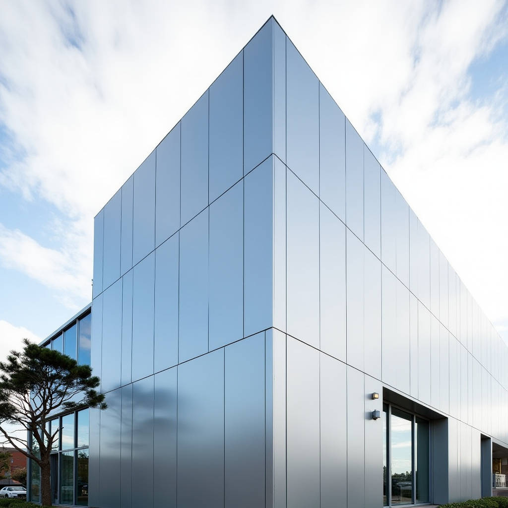
When a project specification calls for a non combustible aluminum panel, most architects and facade consultants immediately think of fire classification reports. That focus makes sense. But there is another dimension that deserves equal attention during the design development phase: wind load resistance. A solid aluminum cladding panel that meets ASTM E84 Class A requirements still needs to withstand the suction and deflection forces that act on a building envelope every day. Ignoring this interaction between fire performance and structural engineering can lead to costly remediation, even if the panel itself carries the correct non-combustibility documentation.
This article examines the structural mechanics of a non combustible aluminum panel under wind loading. It covers the calculation methodology, the role of stiffener design, the impact of span distances on deflection limits, and the specific testing protocols that validate performance. The goal is to give facade engineers, procurement managers, and general contractors a practical framework for specifying solid aluminum cladding that performs under both fire and wind conditions.
Why Wind Load Matters for Non Combustible Aluminum Panel Systems
Building codes treat fire safety and structural integrity as separate chapters. But on the facade, these two requirements intersect. A non combustible aluminum panel achieves its fire classification through material composition: 100% solid aluminum sheet, typically 2.0mm, 2.5mm, or 3.0mm thick, with no combustible core. The panel itself does not contribute to flame spread. However, the same panel must also resist the wind pressures that the building will face over its service life.
The problem arises when project teams treat the non combustible aluminum panel as a commodity item. They verify the fire test report, check the PVDF coating specification, and move on. Wind load calculations get delegated to the structural engineer, who may not be familiar with the specific deflection characteristics of thin-gauge aluminum sheet. The result? Panels that pass fire inspection but exhibit oil-canning, fastener fatigue, or even panel dislodgement during storm events.
ASCE 7-16 provides the baseline for wind load determination across the United States. For a non combustible aluminum panel installed on a mid-rise commercial building in a 115 mph wind zone, the design wind pressure can easily reach 30 to 45 psf on corner zones. That pressure translates into bending moments that the panel and its support system must resist without exceeding allowable deflection limits.
Material Properties That Drive Wind Resistance
Solid aluminum cladding panels start with alloy selection. The industry standard for architectural applications is 3003-H14 or 5052-H32 aluminum alloy. The 3003-H14 alloy offers a tensile strength of approximately 20 to 25 ksi, while 5052-H32 provides higher strength at 31 to 38 ksi. For projects in high-wind zones or coastal environments, the 5052 alloy is often specified because its higher yield strength translates into better resistance to permanent deformation under cyclic loading.
The thickness of the non combustible aluminum panel directly affects its section modulus and moment of inertia. A 2.0mm (0.080") panel has a section modulus roughly 40% lower than a 3.0mm (0.125") panel of the same width. This means the thinner panel will deflect significantly more under identical wind loads. Table 1 below summarizes the key mechanical properties that influence wind load performance.
| Alloy & Temper | Tensile Strength (ksi) | Yield Strength (ksi) | Elongation (%) | Typical Thickness Range |
|---|---|---|---|---|
| 3003-H14 | 20 - 25 | 17 - 21 | 8 - 16 | 2.0mm - 3.0mm |
| 5052-H32 | 31 - 38 | 23 - 28 | 10 - 18 | 2.0mm - 3.0mm |
| 6061-T6 | 42 - 45 | 35 - 40 | 10 - 14 | 2.5mm - 3.0mm |
6061-T6 is less common for architectural cladding due to cost and formability constraints, but it appears in specialized applications where extreme wind loads demand maximum strength. For most commercial projects, 5052-H32 provides the best balance of formability, corrosion resistance, and wind load capacity.
Field Note: On a 22-story tower in Miami, the facade consultant originally specified 3003-H14 at 2.5mm for all non combustible aluminum panel areas. Wind tunnel testing revealed corner zone pressures exceeding 55 psf. The specification was revised to 5052-H32 at 3.0mm with additional intermediate stiffeners. The material cost increase was approximately 12%, but it eliminated the need for post-installation remediation that would have cost five times that amount.
Span, Stiffener Layout, and Deflection Limits
The span distance between supports is the single most influential variable in wind load performance. For a non combustible aluminum panel, the span is typically the distance between horizontal girts or vertical mullions on the curtain wall substructure. Industry practice caps the allowable deflection at L/60 for aluminum cladding panels under design wind load, where L is the span length. Some specifications tighten this to L/90 for spandrel areas or high-visibility elevations.
Consider a 3.0mm thick 5052-H32 panel spanning 600mm (24 inches) between supports. Under a uniform wind pressure of 35 psf, the maximum deflection can be calculated using the formula for a simply supported rectangular plate. Without stiffeners, the deflection may approach 8 to 10mm. That exceeds the L/60 limit of 10mm but only marginally. If the span increases to 900mm (36 inches), the deflection jumps to over 25mm under the same load, far exceeding allowable limits.
Stiffeners solve this problem. Aluminum extrusions or folded sections are bonded or mechanically attached to the rear face of the panel, increasing the effective section depth without increasing the overall panel thickness. A properly designed stiffener layout can reduce deflection by 60% to 80% compared to an unstiffened panel of the same thickness. The trade-off is added fabrication cost and weight. Each stiffener adds approximately 0.3 to 0.5 kg per linear meter, which accumulates across thousands of square meters of cladding.
Stiffener Attachment Methods
There are two primary methods for attaching stiffeners to a non combustible aluminum panel. The first is structural adhesive bonding, using two-part epoxy or polyurethane adhesives. This method distributes stress evenly across the bond line and avoids thermal bridging. The second is mechanical fastening with stainless steel rivets or screws. Mechanical attachment is faster and less sensitive to surface preparation, but it creates point loads that can initiate fatigue cracking under cyclic wind loading.
For high-wind applications, a hybrid approach is gaining traction. The stiffener is bonded with structural adhesive and then secured with a limited number of mechanical fasteners at the ends. This provides redundancy: if the adhesive degrades over decades of thermal cycling, the mechanical fasteners prevent complete stiffener detachment. The approach aligns with recommendations from the AAMA 508 standard for structural silicone and adhesive attachment.
Testing Protocols Beyond Fire Classification
Fire testing for a non combustible aluminum panel typically follows ASTM E84 or EN 13501-1. These tests establish the material's reaction to fire and its classification as non-combustible. But wind load performance requires a different set of tests.
ASTM E330 is the standard test method for structural performance of exterior windows, doors, skylights, and curtain walls by uniform static air pressure difference. For cladding panels, a mock-up assembly is constructed and subjected to both positive and negative pressure cycles. The test measures deflection at specified pressure increments and checks for permanent deformation after the load is removed. A non combustible aluminum panel system should demonstrate full recovery after the design pressure cycle and no failure at 1.5 times the design pressure.
ASTM E1996 and ASTM E1886 address cyclic wind loading and missile impact resistance. These standards are particularly relevant for projects in hurricane-prone regions. The panel must withstand repeated pressure cycles that simulate the fluctuating wind loads of a storm event. A panel that passes static load testing may still fail under cyclic loading if the stiffener bonds or fastener connections degrade over thousands of cycles.
Pro Tip: When reviewing test reports for a non combustible aluminum panel, check whether the testing was performed on the full assembly or just the panel material. A material-only ASTM E84 report tells you nothing about how the panel, stiffeners, and attachment clips perform together under wind load. Always request assembly-level ASTM E330 test data for the specific span and stiffener configuration you intend to use.
Connection Design: The Weak Link in Wind Load Paths
The load path for wind pressure on a non combustible aluminum panel travels from the panel face to the stiffeners, then to the perimeter extrusion or clip system, and finally to the curtain wall substructure. Each connection point in this chain must be sized for the tributary area it serves.
A common failure mode is under-designed panel clips. Consider a panel measuring 1.2 meters wide by 3.0 meters tall, with four clips per vertical edge. Under a design wind pressure of 40 psf, the total load on the panel is approximately 1,550 pounds. Each clip must resist roughly 195 pounds. If the clip is fabricated from 5052-H32 aluminum at 2.0mm thickness, its capacity may be adequate for the design load but insufficient for the safety factor of 1.5 required by many building codes.
Stainless steel clips offer higher capacity but introduce galvanic corrosion risk when in direct contact with aluminum. The solution is a separation layer: a thin EPDM or PVC isolator between the stainless steel clip and the aluminum panel. This detail adds negligible cost but prevents the electrochemical reaction that can compromise the connection over time.
Thermal Movement and Wind Load Interaction
Aluminum expands and contracts at a rate of approximately 0.000023 mm per mm per degree Celsius. A 3-meter panel subjected to a 60°C temperature swing will experience roughly 4.1mm of thermal movement. If the panel is rigidly constrained at all four edges, this movement generates compressive or tensile stresses that combine with wind-induced stresses.
The interaction matters because a non combustible aluminum panel that is tightly fastened on all sides may buckle outward when thermal expansion and wind suction act simultaneously. The buckling amplitude can exceed the flatness tolerance specified in the architectural specification, triggering a rejection even though the panel itself is structurally sound.
The standard remedy is to allow one edge of the panel to slide. Typically, the top edge is fixed and the bottom edge uses slotted holes that permit vertical movement. This detail accommodates thermal expansion without compromising the wind load resistance of the fixed connections. The Aluminum Association publishes detailed guidance on thermal movement accommodation in its Design Manual.
Corner Zones and Edge Effects
Wind tunnel studies consistently show that wind pressures are highest at building corners, roof edges, and parapets. ASCE 7-16 defines these as Zone 5 (corner) areas, where the external pressure coefficient can be 2 to 3 times higher than the field of the wall. A non combustible aluminum panel installed in a corner zone must be designed for these elevated pressures.
Practical implications: the panel thickness, stiffener spacing, and clip count that work for the main facade may be inadequate for corner panels. Some projects specify a single panel type across the entire facade for aesthetic consistency, which means all panels must be designed to the worst-case corner zone pressures. This approach simplifies procurement but increases material cost by 15% to 25% compared to a zone-specific design.
The alternative is to use the same panel thickness and finish across all zones but vary the stiffener layout and clip count. Corner panels receive additional stiffeners and closer clip spacing. The visual appearance remains identical because the panel face and joint widths are unchanged. This approach requires more detailed shop drawings and fabrication tracking but optimizes material usage.
Coastal and High-Wind Project Considerations
Projects in coastal environments face a combination of high wind loads and corrosive salt spray. A non combustible aluminum panel specified for these conditions needs both mechanical strength and corrosion resistance. The 5052-H32 alloy addresses both requirements: its magnesium content provides better saltwater corrosion resistance than 3003 series alloys, and its higher yield strength handles the elevated wind pressures.
PVDF coating systems add another layer of protection. A 70% Kynar 500 PVDF coating with a minimum dry film thickness of 30 microns provides a barrier against chloride ion penetration. The coating specification should reference AAMA 2605, which is the highest performance standard for architectural coatings. AAMA 2605 requires a minimum of 10 years of South Florida exposure testing with specific limits on color change (Delta E ≤ 5.0) and gloss retention (≥ 50%).
For projects in the Middle East, where wind-blown sand adds an abrasive element to the wind load, the coating thickness may need to increase to 40 to 50 microns. Some manufacturers, including Futeng®, offer enhanced PVDF formulations with higher resin content specifically for abrasive environments. The additional coating thickness adds approximately 5% to 8% to the panel cost but significantly extends the service life in harsh conditions.
Specification Language That Protects Against Wind Failure
Specifications that simply call for a "non combustible aluminum panel" without defining wind load requirements leave the project exposed. A robust specification should include the following elements:
- Alloy and temper: Specify 5052-H32 for high-wind or coastal locations; 3003-H14 is acceptable for low-rise inland projects.
- Panel thickness: State the minimum thickness in millimeters or inches. 2.5mm is typical for most applications; 3.0mm for high-wind zones.
- Allowable deflection: L/60 under design wind load as a minimum; L/90 for high-visibility areas.
- Stiffener design: Require shop drawings showing stiffener layout, attachment method, and calculated deflection for each panel type.
- Testing requirements: ASTM E330 assembly testing at design pressure and 1.5x design pressure; ASTM E1996 for hurricane zones.
- Connection design: Clip material, spacing, and capacity calculations signed by a licensed engineer.
- Thermal movement: Details showing how movement is accommodated at panel joints.
This level of detail in the specification documents protects the owner, the design team, and the contractor. It establishes clear performance criteria that the non combustible aluminum panel supplier must meet, and it provides a basis for evaluating substitution requests.
Cost Implications of Wind Load Engineering
Engineering a non combustible aluminum panel system for wind loads adds cost, but the cost is predictable and manageable when addressed early. Table 2 provides a comparative cost breakdown for a typical mid-rise office building with 5,000 square meters of cladding.
| Design Approach | Panel Thickness | Stiffener Density | Relative Cost per m² | Total System Cost |
|---|---|---|---|---|
| Basic (low-wind inland) | 2.0mm 3003-H14 | Minimal | $85 - $105 | $425,000 - $525,000 |
| Standard (moderate wind) | 2.5mm 3003-H14 | Standard | $105 - $130 | $525,000 - $650,000 |
| Enhanced (high-wind/corner) | 3.0mm 5052-H32 | Increased | $130 - $160 | $650,000 - $800,000 |
| Premium (hurricane zone) | 3.0mm 5052-H32 | Maximum + hybrid attachment | $160 - $195 | $800,000 - $975,000 |
The cost difference between the basic and premium approaches is significant, but it represents roughly 2% to 4% of the total curtain wall budget for a typical commercial project. When weighed against the cost of panel replacement, water ingress damage, or litigation following a failure, the investment in proper wind load engineering is modest.
Quality Control During Fabrication and Installation
Wind load performance depends on fabrication quality as much as design. A non combustible aluminum panel with perfectly calculated stiffener spacing will still fail if the adhesive bond is poorly executed. Key quality control checkpoints include:
Surface preparation before adhesive bonding: aluminum surfaces must be cleaned and abraded to remove the oxide layer and any mill oils. The cleaning process should follow the adhesive manufacturer's specifications, typically involving a solvent wipe followed by light abrasion and a second solvent wipe. The prepared surface has a limited open time before bonding must occur.
Adhesive mixing and application: two-part structural adhesives require precise mixing ratios. Automated mixing equipment reduces human error. The adhesive bead must be continuous and of the specified dimensions. Gaps in the bead create stress concentrations that can initiate failure.
Installation torque on mechanical fasteners: over-torqued fasteners can dimple the panel face or strip threads. Under-torqued fasteners may loosen under vibration. A calibrated torque wrench and a defined torque specification, typically 3 to 5 Nm for M6 stainless steel fasteners into aluminum, should be part of the installer's toolkit.
Field verification of panel flatness: after installation, panels should be checked for oil-canning using a straight edge and feeler gauge. The AAMA 508 and 509 documents provide acceptance criteria for panel flatness. Deviations that exceed the specified tolerance should trigger an investigation into whether the stiffener layout or attachment method needs adjustment.
Integrating Wind and Fire Requirements in Procurement
Procurement managers handling a non combustible aluminum panel package face a dual challenge: verifying fire compliance and ensuring structural adequacy. The most efficient approach is to combine both requirements into a single pre-qualification process.
Request the following from potential suppliers at the RFQ stage:
- ASTM E84 or EN 13501-1 test reports for the panel material, confirming non-combustible classification.
- ASTM E330 test reports for the panel assembly at the specified span and stiffener configuration.
- Engineering calculations for deflection and connection capacity, stamped by a licensed professional engineer.
- Project references for installations in similar wind zones.
- Mill certificates for the aluminum coil, confirming alloy and temper.
- Coating performance test data per AAMA 2605.
Suppliers who cannot provide items 2 and 3 should be excluded from consideration, regardless of their fire test documentation. A non combustible aluminum panel that cannot withstand the design wind loads is not a compliant product, even if it carries the correct fire classification.
Futeng® and other established manufacturers maintain comprehensive technical documentation packages that include both fire and structural test data. When evaluating suppliers, the completeness and organization of their technical submittals often indicate the quality of their engineering support throughout the project.
Lessons from Field Failures
Several well-documented facade failures illustrate the consequences of neglecting wind load engineering for non combustible aluminum panel systems. In one case, a 15-story residential tower in a coastal city experienced panel dislodgement during a tropical storm with wind speeds below the design event. The investigation found that the stiffener adhesive had been applied to uncleaned aluminum surfaces, and the bond had degraded to near-zero strength within three years. The panels themselves were non-combustible and met all fire requirements. They simply could not stay attached to the building.
In another case, a low-rise commercial building specified 2.0mm panels without stiffeners to reduce cost. The panels met the fire classification and the static wind load test on a small mock-up. But after installation, thermal cycling combined with moderate wind loads caused progressive oil-canning across 30% of the facade area. The owner accepted the visual defect rather than fund a full replacement, but the project team's reputation suffered.
These failures share a common thread: the project team treated the non combustible aluminum panel as a fire-only specification item and delegated structural performance to the shop drawing phase, where it received insufficient scrutiny. The lesson is clear: wind load engineering must be integrated into the specification and design review process from the outset.
The non combustible aluminum panel is a proven, reliable facade material when properly specified and installed. Its fire performance is inherent in the solid aluminum composition. Its wind load performance, however, depends on deliberate engineering decisions about alloy, thickness, stiffener layout, connection design, and thermal movement accommodation. Facade professionals who address these decisions during design development, rather than deferring them to the submittal phase, will deliver buildings that perform under both fire and wind conditions for decades.