How an Aluminum Panel Manufacturer Engineers Thermal Expansion Joints for High-Rise Curtain Walls
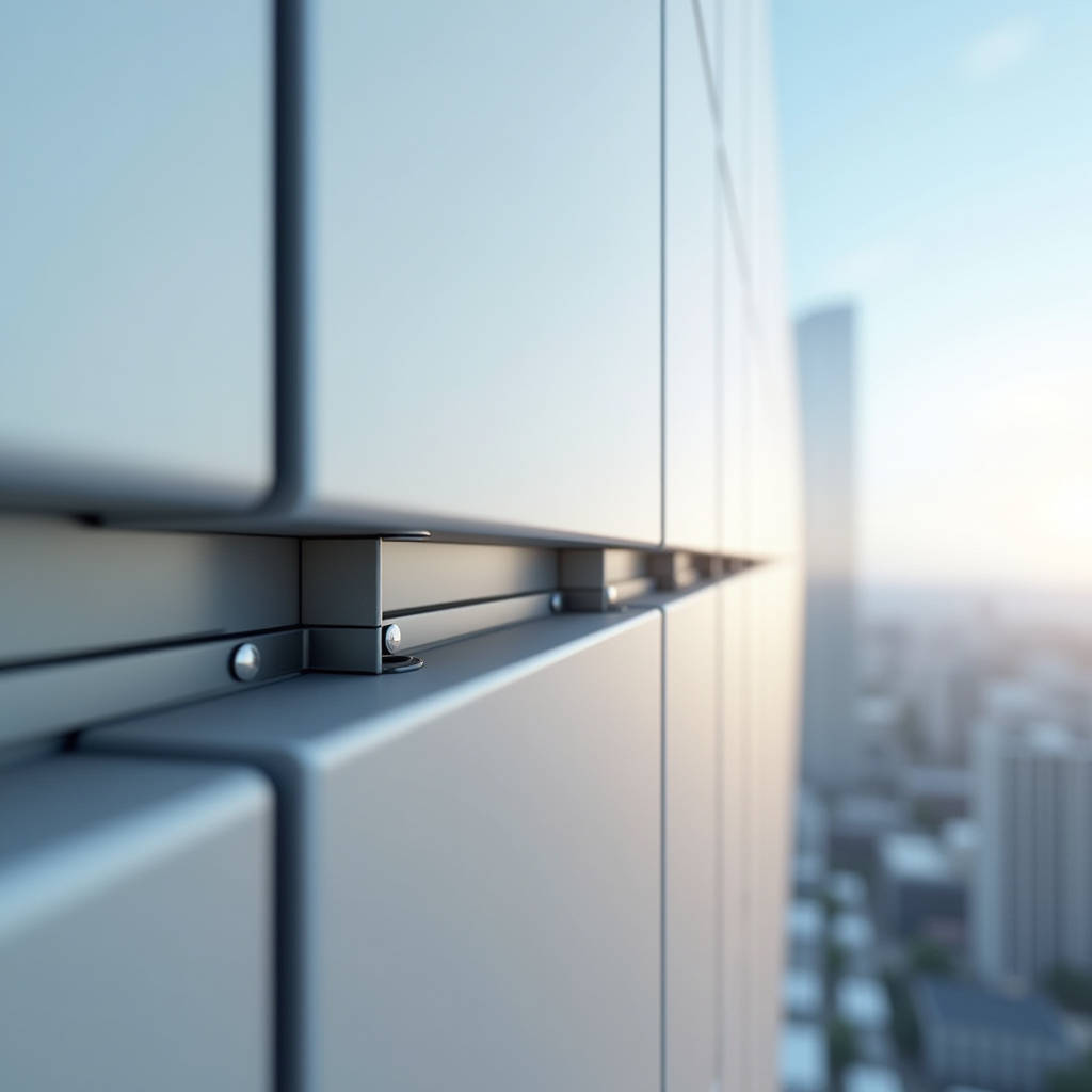
When a façade contractor bids on a 200-meter tower in Doha or a performing arts center in Kuala Lumpur, the conversation rarely starts with "how much per square meter." It starts with what happens when a 3.0mm solid aluminum panel spans 4.2 meters across a curtain wall at 48°C ambient temperature, then cools to 18°C overnight. That 30-degree delta isn't theoretical. It translates into real thermal movement, and if your aluminum panel manufacturer hasn't accounted for it in the extrusion profile, the joint design, and the fixing system, you'll hear the panels creaking before the building is even handed over.
This article drills into one specific problem: the engineering of thermal expansion joints in solid aluminium cladding panels for high-rise curtain wall applications. Not general procurement advice. Not a comparison of material types. Just the physics, the math, the fabrication tolerances, and the on-site coordination that separates a silent façade from one that buckles under its own thermal load.
Why Thermal Movement Destroys Façades That Look Perfect on Paper
Aluminum has a linear thermal expansion coefficient of approximately 23.4 × 10⁻⁶ per °C. That number sounds abstract until you apply it to a 4,000mm panel subjected to a 60°C surface temperature swing — common on dark-colored PVDF-coated panels in Middle Eastern or Southeast Asian climates. The math is straightforward: 4,000 × 23.4 × 10⁻⁶ × 60 = 5.62mm of linear expansion. A single panel grows by over half a centimeter. Multiply that across a 60-meter elevation with 15 rows of panels, and the cumulative movement at the top floor can exceed 80mm if not properly isolated at each floor line.
Most specification writers reference ASTM E228 for thermal expansion testing, but the gap between lab data and installed behavior is where projects go wrong. An aluminum panel manufacturer that only quotes the coefficient without discussing joint geometry, gasket compression, and fixing slot tolerances is handing you a liability, not a solution.
Field Note: On a 42-story project in Jeddah, we measured actual panel surface temperatures of 82°C on dark bronze PVDF panels at 2:00 PM in August. The specification assumed 70°C maximum. The difference added 0.8mm of unplanned movement per panel. We caught it during mock-up testing. If the shop drawings had already been approved without that margin, the contractor would have been replacing gaskets within 18 months.
What the Right Aluminum Panel Manufacturer Engineers Into Every Joint
Thermal movement accommodation isn't a single design decision. It's a chain of interdependent choices that starts at the extrusion die and ends at the silicone sealant joint. Break any link, and the system fails. Here's where the engineering depth of your aluminum panel manufacturer matters.
Fixing Slot Geometry and the Difference Between Restrained and Released Points
Every solid aluminium cladding panel needs a defined fixing regime: typically two fixed points (round holes) and the remainder as sliding points (slotted holes). The slot length isn't guesswork. For a 3.0mm thick panel at 3,500mm length with a 70°C temperature range, the slot needs to accommodate at least 5.7mm of movement in the primary expansion direction. But that's the minimum. A competent aluminum panel manufacturer will specify slots 20-30% longer than the calculated movement to account for installation tolerances and building frame deflection under wind load.
The slot orientation matters equally. Vertical panels on a tower expand primarily in the vertical axis. Horizontal soffit panels expand in both directions. The fixing system — whether it's a cassette system with perimeter extrusions or a tray panel with folded returns — must be designed so that the sliding fixings actually slide. We've seen projects where the slots were correctly sized but the stainless steel screws were over-torqued during installation, effectively locking the panel in place. The first hot day, the panels buckled outward by 8mm at mid-span.
Joint Width, Gasket Compression, and the Silicone Decision
The visible joint between panels serves three functions: accommodating thermal movement, maintaining a weather seal, and achieving the architectural shadow line. Getting all three right requires the aluminum panel manufacturer to coordinate with the gasket supplier and the sealant manufacturer — not just ship panels and walk away.
For a typical unitized curtain wall with solid aluminium cladding panels, joint widths of 15-20mm are common. But the critical number is the movement accommodation factor (MAF) of the gasket or sealant. A high-performance silicone like Dow Corning 791 can handle ±50% movement. That means a 15mm joint can accommodate 7.5mm of movement — adequate for most panel-to-panel joints. But if the design calls for a 10mm joint for aesthetic reasons, the MAF drops to ±5mm, which may be insufficient for long panels in extreme climates.
| Joint Type | Typical Width | Movement Capacity | Best Application | Risk Factor |
|---|---|---|---|---|
| Open joint (drained & ventilated) | 12–20mm | Unlimited (non-sealed) | Rainscreen behind ventilated cavity | Low — requires internal drainage plane |
| Silicone weather seal (field-applied) | 15–25mm | ±50% of joint width | High-rise curtain wall with full air/water barrier | Medium — workmanship-dependent |
| Pre-formed EPDM gasket (compression) | 12–18mm | ±25% of joint width | Unitized systems with factory-installed gaskets | Low-Medium — requires precise panel alignment |
| Butterfly gasket (interlocking) | 8–15mm | ±15% of joint width | Low-rise commercial, interior soffits | Medium — limited thermal range |
| Structural silicone (SSG) butt joint | 6–10mm | ±10% of joint width | Architectural feature joints only | High — not recommended for primary movement joints |
Floor Line Isolation: Where the Real Movement Happens
Individual panel joints handle local expansion. But the big cumulative movement — the 80mm we mentioned earlier — must be absorbed at floor line expansion joints. This is where the curtain wall consultant, the aluminum panel manufacturer, and the structural engineer need to be reading from the same set of drawings.
A floor line joint in a unitized system typically consists of a horizontal expansion profile that allows the panel stack above to move independently of the stack below. The profile itself is often an aluminum extrusion with integrated EPDM gaskets, designed to telescope as the building moves. The specification should call out the expected movement range, and the extrusion should be tested to that range plus a safety factor — typically 1.5× the calculated maximum.
Futeng® has supplied solid aluminium cladding panels for projects where the floor line movement specification reached ±25mm per floor. In those cases, the panel's bottom fixing detail was redesigned with an extended slotted bracket, and the horizontal joint was widened to 35mm with a dual-gasket labyrinth seal. The alternative — trying to absorb all movement in the panel-to-panel joints — would have required 40mm joints that the architect had already rejected on aesthetic grounds.
Thermal Bow: The Problem Nobody Checks Until the Mock-Up
Thermal bow is the out-of-plane deflection of a solid aluminum panel when the front face heats up faster than the back face. A 3.0mm thick panel at 1,200mm wide and 3,600mm long can bow outward by 4-6mm under direct solar exposure. This isn't a material defect — it's basic physics. The front face expands while the back face, shaded by the panel itself, stays cooler. The differential creates a bending moment.
The question is whether your aluminum panel manufacturer accounts for thermal bow in the fixing design. If the panel is fixed too rigidly, thermal bow stress can cause permanent deformation or fatigue cracking at the fixing points over thousands of thermal cycles. The solution is typically a combination of: specifying a minimum panel thickness relative to the span (3.0mm for spans over 3,000mm), designing fixings with enough rotational freedom to accommodate bowing without restraint, and in some cases, adding stiffeners bonded to the back face with structural adhesive.
ASTM E330 (structural performance under static loads) and AAMA 501.5 (thermal cycling) provide testing frameworks, but the most reliable data comes from a full-scale mock-up tested under actual solar conditions. Any aluminum panel manufacturer serious about high-rise work should be able to provide mock-up test reports from previous projects with similar panel dimensions and color ranges.
How Fabrication Tolerances Compound Thermal Problems
Even with perfect engineering, poor fabrication tolerances will eat into your thermal movement budget. If a panel is specified at 3,500mm ±1.5mm but arrives at 3,503mm, that extra 3mm doesn't seem like much. But if the joint is only 15mm wide and the adjacent panel is also 3mm over, you've lost 6mm of your 15mm joint before any thermal movement occurs. On a hot day, the panels close the remaining gap, the sealant extrudes, and you've got a maintenance headache before the building opens.
A reputable aluminum panel manufacturer works to ISO 2768-m tolerances as a baseline, but for high-rise façade work, tighter tolerances are standard: ±1.0mm on panel dimensions, ±0.5mm on squareness (measured diagonally), and ±0.3mm on fold line positions. These numbers should be written into the purchase specification and verified on the first article inspection report (FAIR) before production begins.
Coordinating Panel Delivery With the Erection Sequence
Thermal movement design doesn't end at the factory door. The sequence in which panels arrive on site and are installed affects how the system performs. If panels for a single elevation are fabricated in different production batches with slight color or dimensional variations, the joints won't align uniformly, and the thermal movement capacity becomes unpredictable.
A practical approach that experienced contractors use: specify batch fabrication by elevation and floor level, with each batch clearly labeled and shipped together. The aluminum panel manufacturer should provide a panel schedule that maps every panel to its grid location, including the direction of the slotted holes relative to the building's expansion axes. Panels should be protected during shipping with interleaving foam sheets and edge protectors — FOB/CIF shipments across ocean routes can see humidity cycles that cause micro-corrosion on raw edges if not properly packed.
Pro Tip: When receiving panels on site, spot-check 5% of panels for dimensional accuracy against the shop drawings, not just the purchase order. We've caught cases where the shop drawing revision was updated but the factory was still working to the previous revision. The 2mm difference in slot length would have locked up half the panels on the south elevation.
What to Demand From Your Aluminum Panel Manufacturer Before Production
If you're specifying solid aluminium cladding panels for a project where thermal movement is a genuine concern — and it should be for any building over 10 stories or in a climate with seasonal temperature swings exceeding 40°C — here's the minimum you should require before signing off on production:
- Thermal movement calculation report specific to your project's climate data, panel dimensions, and fixing system. Not a generic datasheet.
- Fixing slot and bracket shop drawings showing the fixed point locations, sliding point slot lengths, and the calculated movement range for each panel type.
- Joint design documentation coordinating the gasket/sealant specification with the calculated joint width, including the movement accommodation factor.
- Mock-up test protocol aligned with ASTM E330, AAMA 501.5, or the local equivalent, with pass/fail criteria for thermal cycling.
- First article inspection report with actual measured dimensions, not nominal values.
These documents should come from the aluminum panel manufacturer's engineering team, not the sales department. If the person signing the thermal calculation doesn't have a structural or mechanical engineering background, ask for someone who does.
The difference between a façade that performs for 30 years and one that needs remedial work in year three often comes down to whether the thermal movement was engineered or assumed. The panels themselves — 2.0mm, 2.5mm, or 3.0mm solid aluminium with PVDF coating — are fundamentally the same material. What changes is the intellectual rigor applied to how they're fixed, jointed, and allowed to move. Choose your aluminum panel manufacturer accordingly.