ACM Cladding Wind Load Engineering for High Rise Façades Without Costly Overdesign
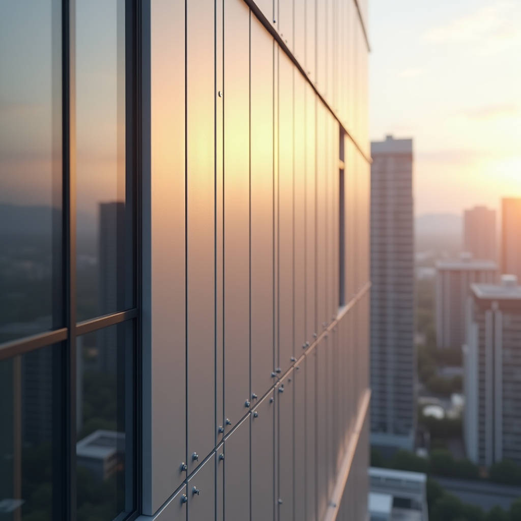
When a 42-storey commercial tower in Kuala Lumpur went into façade design review, the engineering team flagged a single issue that reshaped the entire specification: the building's curved northeast corner would expose ACM cladding panels to a Venturi-effect wind corridor at 140 metres above grade. The fix wasn't thicker panels. It was a complete re-engineering of the fixing system, stiffener layout, and joint geometry — all before a single panel left the factory. This is the reality of high-rise ACM cladding that rarely makes it into generic product brochures: wind load isn't a number you look up in a table. It's a site-specific structural problem that cascades into every decision about panel gauge, anchor spacing, and long-term fatigue performance.
Why Wind Tunnel Data Changes Everything on Tall Façades
Most architectural specifications for ACM cladding reference a design wind pressure in kilopascals (kPa) pulled from the local building code. That works for low-rise and mid-rise structures. Above roughly 80 metres, the assumptions baked into those code tables start to break down. Wind speed increases with height, but the pressure distribution across a building face is never uniform. Corners see suction forces 2.5 to 3 times higher than the centre of the wall. Re-entrant corners, balconies, and stepped massing create localised turbulence that code-level calculations simply don't capture.
On a recent project in Ho Chi Minh City, the specified design pressure was 2.8 kPa based on the national standard. A wind tunnel study — conducted after the client questioned why nearby buildings of similar height showed panel deformation within five years — returned peak negative pressures of 6.1 kPa at the upper corner zones. That's a 118% increase. The original 2.0mm solid aluminium panels with 600mm stiffener spacing would have been borderline at best. At 6.1 kPa, a 2.0mm panel spanning 600mm between stiffeners exceeds the L/90 deflection limit under serviceability loads. The revised specification moved to 3.0mm thick panels with 400mm stiffener spacing in corner zones, and 2.5mm elsewhere.
Field Note: Wind tunnel reports typically provide pressure coefficients (Cp) for dozens of zones across the building envelope. Don't let the structural engineer apply a single worst-case value to the entire façade. That's a fast track to an over-engineered, over-budget cladding package. Zone the panel thicknesses and stiffener layouts to match the actual pressure map. The material cost savings from thinning panels in low-pressure zones often cover the cost of the wind tunnel study itself.
Reading Between the Lines of EN 1991-1-4 and ASCE 7
Two standards dominate wind load calculations for ACM cladding on international projects: Eurocode EN 1991-1-4 and the American ASCE 7. Both are legitimate starting points. Neither is sufficient on its own for a building over 100 metres.
EN 1991-1-4 uses a detailed pressure coefficient approach that differentiates between windward, leeward, and side faces. It also accounts for the building's aspect ratio and surrounding terrain roughness. The limitation: the standard pressure coefficients are derived from rectangular prism models. Introduce a curved façade, a tapered crown, or a porous screen element, and you're outside the validated range of the code. The Eurocode itself acknowledges this in Annex D, which states that non-rectangular shapes require wind tunnel or CFD analysis.
ASCE 7 takes a different approach. The directional procedure in Chapter 27 provides a streamlined calculation path that many US-based consultants default to. The problem is the gust effect factor — a single coefficient meant to capture dynamic amplification. For a slender 50-storey tower with a natural frequency below 1 Hz, that single coefficient masks significant resonant effects. The more rigorous Chapter 31 wind tunnel procedure is what you actually need, but it's often skipped in preliminary design stages to save time and cost. By the time the ACM cladding package goes to tender, the wind loads are locked into the specification, and correcting them mid-procurement is a contractual mess.
The practical takeaway for façade contractors and procurement managers: when reviewing a tender package for ACM cladding on any building over 80 metres, ask for the wind tunnel report. If it doesn't exist, price the risk. A 15-20% contingency on panel thickness and fixing density is not unreasonable when the alternative is a five-figure remediation bill five years after handover.
Panel Gauge, Stiffener Design, and the Deflection Limit Nobody Agrees On
Once the design pressures are established, the engineering focus shifts to the aluminium panel itself. Solid ACM cladding panels — typically 2.0mm, 2.5mm, or 3.0mm thick in grades AA1100, AA3003, or AA5052 — behave as thin plates under uniform lateral load. The maximum deflection depends on panel thickness, stiffener spacing, edge restraint conditions, and the aluminium alloy's modulus of elasticity.
The industry standard deflection limit for ACM cladding under wind load is L/90 for the panel span between stiffeners, where L is the shorter dimension of the panel sub-area. Some specifications push this to L/120 for prestige projects where visible waviness under wind is unacceptable. Here's where it gets contentious: L/90 is a serviceability criterion, not a safety criterion. A panel deflecting to L/60 won't fail structurally, but it will look terrible in raking light, and the cyclic movement will accelerate fatigue at the fixing points. I've seen projects where the specifier wrote L/90 in the performance specification but the contractor's shop drawings calculated everything at L/60 — and nobody caught it until the first panels were installed and the client's representative noticed the oil-canning effect on a sunny afternoon.
The table below provides a practical reference for solid aluminium panel deflection under uniform pressure, based on a simply supported two-way spanning condition with full edge restraint. These are not design values — every project needs its own calculations — but they give a realistic sense of how panel thickness and stiffener spacing interact.
| Panel Thickness | Stiffener Spacing | Pressure (kPa) | Max Deflection | Deflection Ratio | Serviceability Verdict |
|---|---|---|---|---|---|
| 2.0mm (AA3003 H14) | 500mm | 2.0 | 6.8mm | L/73 | Marginal — exceeds L/90 |
| 2.0mm (AA3003 H14) | 400mm | 2.0 | 4.1mm | L/98 | Pass — L/90 satisfied |
| 2.5mm (AA3003 H14) | 600mm | 3.0 | 7.5mm | L/80 | Marginal — exceeds L/90 |
| 2.5mm (AA3003 H14) | 500mm | 3.0 | 4.8mm | L/104 | Pass — L/90 satisfied |
| 3.0mm (AA5052 H32) | 600mm | 4.0 | 5.9mm | L/102 | Pass — L/90 satisfied |
| 3.0mm (AA5052 H32) | 500mm | 4.0 | 3.7mm | L/135 | Pass — L/120 satisfied |
Note the alloy shift at 3.0mm. AA5052 offers roughly 15% higher yield strength than AA3003, which matters when you're pushing the panel gauge to manage weight and cost simultaneously. For projects specifying PVDF-coated ACM cladding with a 3.0mm base metal, AA5052 H32 is the standard recommendation from manufacturers like Futeng®, who stock this alloy specifically for high-wind applications.
Fixing Systems Under Cyclic Loading: The Fatigue Problem
Wind doesn't push steadily. It gusts, it pulses, and at certain wind speeds it can lock into vortex shedding frequencies that make the whole building sway. For ACM cladding, this translates into millions of small load cycles over the design life of the building. The panels themselves are rarely the fatigue bottleneck — aluminium has a well-characterised fatigue curve, and the stress levels in a properly designed panel are well below the endurance limit. The problem lives in the fixings.
A typical ACM cladding panel is secured with aluminium extruded clips or brackets that engage a carrier rail system. Under negative wind pressure (suction), the clip is in tension. Under positive pressure, it's in compression. The alternating load path runs through a small contact area — often just a few square millimetres of aluminium-to-aluminium bearing. Over 20 to 30 years of wind cycling, fretting corrosion can initiate at the contact point, particularly in coastal environments where chloride-laden air accelerates the process.
Three practical measures reduce this risk:
- Specify stainless steel grade 316 (not 304) for all fixings within 5 kilometres of a coastline. The molybdenum content in 316 provides meaningful resistance to pitting corrosion in chloride environments. The cost premium over 304 is around 20-25% on the fixing package, which is negligible against the total ACM cladding budget.
- Require a minimum bearing area at clip-to-rail connections. A common rule of thumb is 50mm² minimum contact area per fixing point. Smaller contact areas concentrate stress and accelerate fretting.
- Insist on a cyclic test report for the specific fixing system, not just a static pull-out test. A reputable system supplier will have tested to at least 10,000 cycles at the design load. Ask for the test data. If they can't produce it, find another system.
Pro Tip: When reviewing fixing system shop drawings, check the clip engagement depth. A clip that engages only 3-4mm into the panel return leg leaves almost no tolerance for installation misalignment. Aim for 6-8mm minimum engagement. This sounds like a small detail. It's the difference between a panel that stays put in a typhoon and one that doesn't.
Thermal Movement: The Gap That Engineers Forget
Aluminium expands at roughly 2.4mm per metre per 100°C temperature change. A 3-metre-tall ACM cladding panel on a south-facing façade in Dubai can see a surface temperature swing from 15°C at night to 80°C under direct summer sun — a 65°C delta. That's 4.7mm of linear expansion per panel. If the joint between adjacent panels is only 8mm wide (a common aesthetic choice), more than half the gap is consumed by thermal movement alone, leaving almost nothing for installation tolerance and building movement.
The calculation is straightforward, but the implications ripple through the entire detailing package:
- Joint width must accommodate thermal expansion, floor-to-floor deflection, and a reasonable installation tolerance — typically 3-5mm for a well-executed ACM cladding installation.
- For dark-coloured PVDF finishes (which absorb more solar radiation), add 15-20% to the calculated thermal movement. A black panel can run 10-15°C hotter than a white one on the same façade.
- Fixing clips must allow for in-plane sliding. A rigidly fixed clip that constrains thermal movement will transfer the expansion force into the panel edge, causing local buckling or popping noises that occupants will definitely notice.
The joint width calculation for a typical 3-metre panel in a hot climate works out to: 4.7mm (thermal) + 3mm (deflection) + 4mm (installation tolerance) = 11.7mm minimum. Round up to 12mm. If the architect insists on 8mm joints for aesthetic reasons, the conversation needs to shift to either reducing panel height (more panels, more cost) or accepting the risk of panel-to-panel contact under extreme conditions.
Specifying ACM Cladding for Wind: A Checklist for Tender Documents
Too many tender packages for ACM cladding copy-paste wind load clauses from previous projects without checking whether the numbers actually match the building. The result is either a non-compliant installation or a costly post-tender variation when the contractor's engineer picks up the discrepancy. Here's what a proper wind-related specification section should include:
- Reference the specific wind tunnel report (report number, date, and testing laboratory) — not just "wind loads as per ASCE 7."
- Provide the zoned pressure map showing design pressures for each distinct area of the façade. Corner zones, mid-wall zones, and parapet zones will have different requirements.
- State the deflection limit explicitly — L/90 minimum, L/120 for visible areas if required. Don't leave it to the contractor to guess.
- Define the cyclic test requirement for the fixing system. "Static pull-out test to 1.5x design load" is not enough for a high-rise. Add a cyclic component.
- Specify the corrosion category per ISO 12944-2 (C1 to C5) based on the site's environmental exposure. This drives the fixing material grade and any additional coating requirements.
- Require a thermal movement calculation as part of the shop drawing submission, with joint widths dimensioned to accommodate the calculated range.
For reference, the ISO 12944-2:2017 standard provides the definitive framework for classifying atmospheric corrosivity, which directly informs material selection for ACM cladding fixings in coastal and industrial environments. Similarly, the American Architectural Manufacturers Association (AAMA) publishes testing protocols for curtain wall components that are widely referenced in North American specifications.
When the Wind Load Numbers Don't Add Up: Case Examples
A 38-storey residential tower in Singapore specified ACM cladding with 2.0mm panels and 600mm stiffener spacing across the entire façade. The wind tunnel report — commissioned late in the design phase — showed corner zone pressures of 4.2 kPa. The original panel configuration would have deflected to approximately L/65, well beyond the L/90 limit. The fix involved three changes: upgrading corner zone panels to 2.5mm, reducing stiffener spacing to 450mm in those zones, and adding intermediate fixing clips at panel edges. The additional material cost was approximately 8% of the original ACM cladding package. The alternative was a façade that would have shown visible distortion within the first monsoon season.
In contrast, a 22-storey office building in Warsaw was over-specified. The design called for 3.0mm panels with 400mm stiffener spacing across the entire envelope, based on a conservative interpretation of EN 1991-1-4. Wind tunnel testing showed peak pressures of only 2.1 kPa. The contractor proposed a value-engineering exercise: 2.0mm panels with 500mm stiffener spacing in mid-wall zones, retaining 2.5mm at corners. The material cost saving was 14%, and the revised design still met L/90 deflection limits with margin to spare. The key lesson: wind tunnel data can save money as easily as it can prevent failures.
Getting the Supply Chain Aligned with the Engineering
The engineering is only as good as the fabrication. A panel designed for 3.0mm thickness with 400mm stiffener spacing needs to arrive on site exactly as drawn. This means the stiffener extrusion profile, the bond between stiffener and panel (typically structural adhesive or welded studs, depending on the system), and the clip attachment points all need to match the calculation assumptions.
For international projects, the supply chain adds another layer of complexity. ACM cladding panels fabricated in one country and shipped to another must survive ocean freight without distortion. A panel that leaves the factory flat can arrive with a 2-3mm bow if the crating doesn't properly support the panel edges. That bow might be within the installation tolerance for a low-rise project, but for a high-rise with tight deflection limits, it eats into the margin you've engineered for wind performance.
Specify the packaging standard in the purchase order. Vertical crating with edge protection, interleaving with foam or kraft paper, and clearly marked "Do Not Stack" labels are minimum requirements for solid ACM cladding panels over 2.5 metres in any dimension. For panels with PVDF finishes, the interleaving material must be pH-neutral to avoid any chemical interaction with the coating during transit.
The ASTM B209/B209M standard for aluminium sheet and plate provides the material specification baseline that most international ACM cladding projects reference. For coating performance, ASTM D2244 governs colour tolerance measurement, and the Kynar 500® resin specification (minimum 70% PVDF by weight in the colour coat) remains the industry benchmark for long-term exterior durability.
Wind load engineering for ACM cladding isn't the most glamorous part of façade design. It doesn't appear in architectural renderings. It doesn't win design awards. But it's the difference between a building that looks exactly as intended for 30 years and one that needs a reclad before the first tenant lease expires. If you're writing a specification, reviewing a tender, or signing off on shop drawings, the time spent interrogating the wind load assumptions is never wasted.