Managing Dimensional Tolerance Stacks for Standing Seam Aluminum Panels
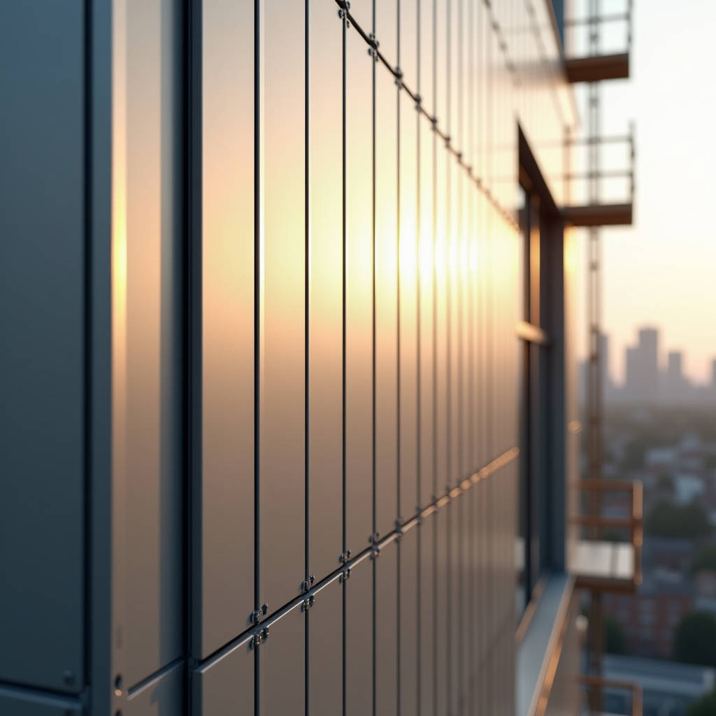
Standing seam aluminum panels represent one of the few façade systems where the joint geometry itself becomes the primary design feature, not an afterthought to be concealed. For commercial projects—airport terminals, convention centers, high-end corporate headquarters—the continuous vertical or near-vertical seam lines create a rhythm across the building envelope that few other cladding materials can replicate. But the visual payoff depends entirely on getting the seam profile, panel flatness, and joint alignment right during the engineering and installation phases. A 1.5mm deviation in seam alignment across a 40-meter elevation is visible from street level, and once the scaffolding drops, there is no fixing it without tearing panels off. This article focuses on the dimensional tolerance stack that governs standing seam aluminum panel performance, from coil flatness at the mill to field-adjustable clip systems that absorb substrate irregularities.
The Seam Profile Decision: Not All Standing Seams Are Equal
Before discussing tolerances, the seam profile itself needs definition. Three dominant profiles exist in the solid aluminum cladding market, and each imposes different fabrication constraints:
- 90-degree lock-seam (single-fold): The most common profile. Panels are formed with a 25–32mm return leg on each side. Adjacent panels interlock and are mechanically seamed on-site. Works well for 2.0mm and 2.5mm thick aluminum. Minimum panel width is typically 250mm; narrower panels become difficult to seam without distortion.
- 180-degree double-lock (double-fold): Common in European roofing-to-wall transitions. Requires 2.5mm minimum thickness because the double fold introduces significant cold-working stress at the seam root. The extra material in the fold adds approximately 0.8 kg/m² to the panel weight compared to single-fold, which matters when calculating dead load on the support structure.
- Trapezoidal standing seam (snap-lock): A clip-based system where panels snap over a concealed clip rail. Popular for ventilated rain-screen applications. The seam height is typically 38–50mm, creating a pronounced shadow line. This profile forgives more substrate irregularity than lock-seam systems because the clip allows ±3mm of thermal movement per panel.
The profile choice cascades into every downstream tolerance decision. A 90-degree lock-seam demands tighter fabrication tolerances than a snap-lock system because the interlock has no built-in adjustment range.
Field Note: On a recent 12,000 m² office tower in Singapore, the contractor initially specified a 180-degree double-lock profile for the entire elevation. The fabricator pushed back—at 2.0mm thickness, the double-fold seam showed micro-cracking at the fold line during bending trials. The spec was revised to 2.5mm 3003-H14 alloy, adding roughly 14% to the material cost but eliminating the fracture risk. The lesson: seam profile and alloy temper must be specified together, not independently.
Coil Flatness: The Tolerance That Starts Before Fabrication
Panel flatness is not something a fabricator can fully correct downstream. It starts with the aluminum coil. ASTM B209 governs aluminum sheet and plate tolerances, but the standard flatness tolerance for H14 temper sheet is 6mm over a 600mm span—far too loose for standing seam aluminum panels where oil-canning (visible waviness) is unacceptable on a smooth, uninterrupted seam face.
For architectural standing seam applications, the practical flatness requirement is closer to 3mm over a 1,200mm span, measured with a straightedge placed diagonally across the panel. Achieving this means specifying:
- Pre-leveled coil: The coil must go through a tension leveler at the mill, not just a roller leveler. Tension leveling elongates the strip by 0.5–1.5% under controlled tension, permanently relieving internal stresses that cause oil-canning after slitting and fabrication.
- Alloy selection: 3003-H14 is the workhorse alloy for standing seam panels. 5052-H32 offers higher strength but is more prone to springback during bending, which complicates seam geometry. Some fabricators blend 3003 for the panel body with 5052 for the clip extrusion, but this introduces galvanic compatibility questions that need answering.
- Mill certification: Require mill test reports (MTRs) showing actual flatness measurements, not just a statement of compliance with ASTM B209. Reputable suppliers like Futeng® provide batch-specific flatness data as part of their standard documentation package for standing seam projects.
Fabrication Tolerance Stack: Where the Seam Gets Defined
Once the coil is flat, the fabrication process introduces its own tolerance chain. For standing seam panels, the critical dimensions are:
| Parameter | Target Tolerance | Measurement Method | Impact if Exceeded |
|---|---|---|---|
| Panel width (coil-to-coil) | ±0.5mm | Digital caliper at 3 points per panel | Seam gap variation; visible misalignment |
| Return leg height | ±0.3mm | Height gauge on both edges | Uneven seam engagement depth |
| Panel length | ±1.0mm per 3m | Tape measure under 5kg tension | Accumulation error at expansion joints |
| Fold angle (lock-seam) | 90° ±0.5° | Digital protractor | Seam won't close fully; water ingress risk |
| Hole position (clip slots) | ±0.3mm | CNC verification report | Clip misalignment; panel won't engage |
| Panel bow (lengthwise) | ≤2mm per 3m | Straightedge + feeler gauge | Visible curvature along seam line |
These are not theoretical numbers. They come from field experience across multiple projects where standing seam aluminum panels were installed at heights exceeding 30 meters. The ±0.5mm width tolerance is particularly unforgiving: across 20 panels installed side-by-side, a consistent +0.5mm error accumulates to 10mm of extra width that the last panel cannot absorb. The fix is either a custom-width filler panel (expensive, slow) or forcing panels into compression (risk of buckling under thermal load).
CNC turret punch and press brake technology has made these tolerances achievable at scale. A modern fabrication line with automatic sheet loading, servo-driven bending, and in-line dimensional inspection can hold ±0.3mm on panel width for runs of 5,000+ panels. The key is statistical process control (SPC) during production, not post-production sorting.
Thermal Movement: The Hidden Tolerance Multiplier
Aluminum expands at approximately 2.4mm per meter per 100°C temperature change. A 4-meter panel subjected to a 60°C surface temperature swing (common on dark-colored PVDF coatings in summer) will grow by roughly 5.8mm. If the standing seam system does not accommodate this movement, the panels will buckle at the seams or tear out the fasteners.
The industry standard for standing seam aluminum panels is to design each panel as a simply supported element with one fixed point and one sliding point. The fixed point is typically at the panel's midpoint, with the clip system allowing ±3mm of longitudinal movement at each end. For panels longer than 4 meters, intermediate sliding clips are added at 1.2–1.5m centers.
Per AAMA 501.4 guidelines, the recommended minimum joint width for thermal movement in aluminum cladding is calculated as:
Joint width ≥ (Coefficient of thermal expansion × Panel length × ΔT) + 3mm safety margin
For a 3.5m panel with a 70°C temperature range, this works out to approximately 8.9mm. Rounding up to 10mm provides a practical joint width that also accommodates minor fabrication and installation tolerances.
Pro Tip: Dark-colored standing seam panels (charcoal, black, deep bronze) can reach surface temperatures of 80°C+ in direct sunlight, even in temperate climates. When specifying PVDF coatings in dark colors, ask the coating supplier for the Total Solar Reflectance (TSR) value. A TSR below 25% means the panel will absorb significant heat. If the structural engineer hasn't accounted for this in the thermal movement calculation, flag it before the shop drawings are approved.
Substrate Tolerance and the Clip System Interface
The cleanest fabrication tolerances mean nothing if the substrate—the steel or aluminum subframe the panels attach to—is out of position. In practice, structural steel tolerances per AISC 303 allow ±6mm in column position over 30 meters. Curtain wall mullion tolerances are tighter, typically ±3mm per floor, but still accumulate.
The standing seam clip system is the interface that absorbs this mismatch. Three clip types dominate:
- Fixed clip: Provides the panel's anchor point. No movement accommodation. Positioned at the panel's thermal center.
- Sliding clip: Allows longitudinal movement via an elongated slot. The slot length is calculated from the thermal movement analysis. Typically ±3mm to ±5mm of travel.
- Adjustable clip: Incorporates a shim or threaded adjustment for out-of-plane alignment. Adjustable range is typically 0–15mm. Used where the substrate is known to be irregular, such as retrofits over existing masonry.
The clip material matters. Stainless steel 316 (A4) clips are standard for exterior applications. Aluminum clips (6063-T6) are lighter but require a protective barrier (typically a 0.5mm PVC isolation pad) between the clip and the steel subframe to prevent galvanic corrosion. Per ISO 9223, environments classified as C4 or higher (coastal, industrial) should use 316 stainless clips exclusively, with no aluminum-to-steel contact anywhere in the assembly.
PVDF Coating: The Tolerance That Affects Appearance
Standing seam panels expose large, uninterrupted surfaces. Any color variation between adjacent panels becomes immediately obvious because the seam line draws the eye along the panel edge. The coating specification must address two tolerances that standard architectural specs often overlook:
Delta E (ΔE) between panels: The industry standard for architectural PVDF coatings is ΔE ≤ 1.0 when measured per ASTM D2244. For standing seam applications, this should be tightened to ΔE ≤ 0.5 for panels installed on the same elevation. This requires the fabricator to produce all panels for a given elevation from the same coil batch and the same coating batch. Even then, panels from the start and end of a coating run can show slight drift. A responsible fabricator will sort panels by measured color value and sequence them on the building to minimize visible transitions.
Coating thickness uniformity: PVDF coatings are typically specified at 25–35μm total dry film thickness (DFT) for a 2-coat system and 35–45μm for a 3-coat system. The tolerance per AAMA 2605 is ±5μm. On a standing seam panel, thickness variation near the fold line can cause the coating to crack during bending. The solution is to specify a minimum 25μm DFT at the bend radius, verified by cross-sectional microscopy on a bend-test coupon from each production batch.
Kynar 500® or Hylar 5000® resin must constitute at least 70% of the total resin solids in the PVDF coating. This is non-negotiable for exterior durability. Some lower-cost suppliers offer "PVDF-type" coatings with 50% resin content—these will chalk and fade within 5–7 years. Demand a coating supplier certificate naming the resin grade and percentage.
Packaging and Logistics: Preserving the Tolerance Chain
A panel that leaves the factory within ±0.5mm tolerance can arrive on site with a 3mm bow if the packaging is inadequate. Standing seam panels are particularly vulnerable because the formed return legs create a stiff edge that concentrates impact forces.
For ocean freight (FOB/CIF shipments), the minimum packaging standard should be:
- Each panel separated by a 3mm PE foam interlayer, not just kraft paper.
- Panels stacked face-to-face and back-to-back in bundles of 20–25 panels maximum. Heavier bundles cause the bottom panels to deform under their own weight during container transit.
- Bundles wrapped in VCI (volatile corrosion inhibitor) film for shipments exceeding 4 weeks in transit.
- Wooden crating with 18mm plywood bases and 12mm side panels. The crate must be strapped, not nailed, to the pallet base to prevent nail-head impressions on the panel surface.
- Each crate labeled with panel sequence numbers matching the installation drawings. This allows the site team to unload in installation order, reducing handling.
Upon arrival, panels should be stored flat on a level surface, still in their crates, in a dry, covered area. If panels must be stored vertically, they need continuous support along the full length of the bottom edge—never rest them on two points, which will induce a permanent bow within 48 hours.
Installation: The Final Tolerance Gate
The site team inherits the entire tolerance chain. Their job is to manage what remains. The critical installation tolerances for standing seam aluminum panels are:
- Seam alignment: ±1.5mm deviation from the theoretical seam line, measured with a laser or taut wire over the full elevation.
- Panel flatness after installation: ≤3mm deviation over a 1,200mm straightedge, per ASTM E1155 floor flatness standards adapted for walls.
- Clip fastener torque: Per manufacturer specification, typically 8–12 Nm for stainless self-tapping screws into steel subframe. Under-torqued clips allow panel movement; over-torqued clips strip threads and lose holding power.
The most common installation error is forcing a panel into a clip that doesn't align. The installer uses a rubber mallet to "persuade" the panel, which deforms the return leg and creates a visible wave at the seam. The correct response to a misaligned clip is to stop, measure the deviation, and adjust the clip position—not the panel.
When the Tolerance Chain Fails: Diagnosis and Remediation
On a completed elevation, tolerance failures present as:
- Seam shadow variation: The shadow line cast by the standing seam changes width along the panel length. This means the panel is bowed or the seam is not fully engaged.
- Oil-canning: Visible waviness across the panel face, most noticeable in low-angle morning or evening light. This is almost always a coil flatness issue, not an installation problem.
- Seam separation: Panels visibly pulling apart at the seam, typically at the top or bottom of the elevation. This indicates thermal movement exceeding the clip's sliding range.
Remediation options are limited and expensive. For oil-canning, the only reliable fix is panel replacement with material from a pre-leveled coil. For seam separation, additional sliding clips can sometimes be retrofitted if the panel can be temporarily unseamed. For alignment issues, adjustable clips can be swapped in, but this requires removing and reinstalling the affected panels.
The cost of remediation typically runs 3–5 times the original installation cost per square meter. The most cost-effective strategy is to catch tolerance issues at the fabrication stage, before panels ship. A pre-shipment inspection (PSI) that includes dimensional sampling of 5% of panels per batch, plus a trial assembly of 10 consecutive panels on a level surface, will identify most tolerance problems before they leave the factory.
Standing seam aluminum panels reward precision. The engineering is straightforward—the discipline to maintain tolerances across every link in the chain, from mill to site, is what separates a façade that reads as crisp and intentional from one that looks like it was assembled by approximate agreement. For project teams specifying these systems, the single most valuable document is not the architectural specification but the fabricator's quality control plan, with actual measurement data, not just compliance statements.