Aluminum Canopy Panels Flatness Tolerance Joint Design and PVDF Coating Field Guide
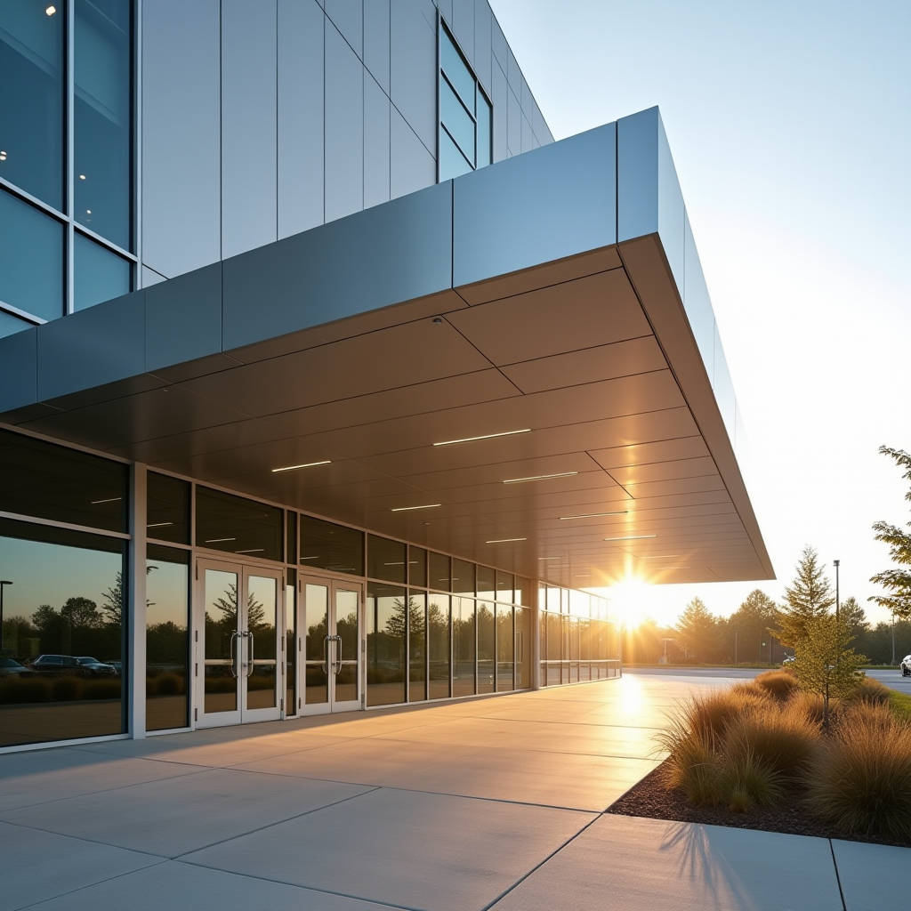
When an architect specifies aluminum canopy panels for a commercial entrance, the drawing rarely tells the full story. The rendering shows clean lines, uniform color, and flush joints. What it does not show is the 3mm tolerance stack-up across a 12-meter welded steel subframe, or the way morning light at a 15° angle exposes every ripple in a panel that looked perfectly flat under shop lighting. This is the gap between design intent and installed reality — and it is where most canopy projects either succeed or fail quietly. We are going to look at what it actually takes to get flatness, joint alignment, and coating consistency right on architectural canopies, drawing from field experience across projects in Southeast Asia, the Middle East, and North America.
Why Canopy Panel Flatness Is a Different Problem Than Wall Cladding
Wall panels hang vertically. Gravity works with the fixing system. Canopy panels sit overhead, often spanning 1,200mm to 1,800mm between support members, and they face a completely different set of forces. Wind uplift on a canopy soffit can exceed 2.0 kPa in coastal zones — that is pulling the panel away from its supports, not pressing it against them. Add thermal expansion across a south-facing aluminum surface that hits 70°C in summer, and you have a panel that is constantly moving.
The flatness tolerance that matters for aluminum canopy panels is not the mill tolerance. ASTM B209 allows 0.4% of length for flatness on 2.5mm sheet — that is 4.8mm deviation across a 1,200mm panel. That number is useless for a canopy soffit where adjacent panels need to read as a single plane from 3 meters below. Our shop standard at Futeng® is 1.5mm maximum deviation across any 1,000mm span, measured after routing and folding, not before. This requires a different approach to stiffener placement.
Field Note: We have seen contractors reject panels on site because they checked flatness with the panel leaning against a wall. A panel that is not supported at its fixing points will always show deflection. Always check flatness with the panel laid horizontally on a calibrated flat table, or better, temporarily fixed to a rigid test frame at the actual fixing centers.
Stiffener Design: Bonded vs. Mechanically Fixed
There are two schools of thought on keeping aluminum canopy panels flat. The first uses continuous aluminum stiffeners mechanically fixed to the rear skin with stainless steel rivets. The second uses galvanized steel stiffeners bonded with structural adhesive. Both work. Both fail when applied to the wrong situation.
Mechanically fixed stiffeners introduce point loads. On a 2.5mm panel, the rivet head creates a micro-depression that can telegraph through to the face under certain light conditions — particularly on dark PVDF colors with a gloss finish. The advantage is that the connection does not degrade over time. Bonded stiffeners distribute load more evenly and eliminate rivet read-through, but the adhesive bond is only as good as the surface preparation. We specify a minimum 95% contact area verified by peel testing on sample coupons for every batch. For canopies in coastal environments, the adhesive must also resist hydrolysis — not all structural adhesives do.
| Stiffener Type | Panel Thickness Range | Max Span Between Stiffeners | Risk of Face Read-Through | Recommended Application |
|---|---|---|---|---|
| Aluminum angle, riveted | 2.5mm – 3.0mm | 600mm | Moderate (visible on gloss dark colors) | Interior canopies, light colors, matte finishes |
| Galvanized steel, bonded | 2.0mm – 3.0mm | 500mm | Low | Exterior canopies, all colors, coastal zones |
| Aluminum hat section, bonded | 2.5mm – 3.0mm | 700mm | Very Low | Large-format panels (1,500mm+), premium projects |
| No stiffener (returns only) | 3.0mm minimum | 400mm | None | Small panels under 600mm, deep returns (40mm+) |
Joint Design: The 8mm Rule and When to Break It
Walk under a well-executed canopy and you will not notice the joints. That is the point. The standard open joint on aluminum canopy panels is 8mm to 12mm, designed to accommodate thermal movement while maintaining a consistent shadow line. The math is straightforward: aluminum expands at 0.024mm per meter per degree Celsius. A 3-meter panel facing a 50°C temperature swing moves 3.6mm. An 8mm joint gives you roughly 4mm of movement on each side before panels touch. That works on paper.
What paper does not capture is the cumulative effect of installation tolerance. If the subframe is out by 3mm and the panel fabrication tolerance is ±1.5mm, you have already consumed 4.5mm of your 8mm joint before thermal movement even enters the equation. This is why we recommend a minimum 10mm joint for canopy soffits when the panel dimension exceeds 1,500mm in any direction. The extra 2mm costs nothing in appearance — from 3 meters below, the difference between an 8mm and 10mm shadow gap is invisible to the human eye — but it buys you a significant margin against panel contact.
Drainage: The Overlooked Detail
Canopy panels are not waterproof membranes. Water will get past the face — through open joints, around perimeter flashings, and via condensation on the rear surface. The question is whether it drains or pools. We see too many specifications that treat the canopy soffit as if it were a vertical wall, with no provision for drainage at the low points.
For any canopy with a slope less than 3°, specify a drained joint system. This means the joint profile includes a concealed gutter channel behind the panel face, sloped independently toward the perimeter. The panel itself stays flat and horizontal; the drainage happens behind it. For canopies with a slope of 3° or more, the panel joints can serve as drainage paths if they are open and the subframe is detailed to prevent water tracking along horizontal members.
PVDF Coating on Canopy Panels: What the Warranty Actually Covers
A 20-year PVDF warranty sounds reassuring. Read the fine print. Most PVDF coating warranties for aluminum canopy panels cover film integrity — the coating will not peel, crack, or chalk beyond a certain threshold. They do not cover color change below 5 Delta E units, and they specifically exclude panels installed within 500 meters of breaking surf or industrial emissions. If your project is a beachfront hotel in Phuket or a terminal at Jeddah's port, you need to know this before you order.
The coating system that works for canopy applications is a 3-coat PVDF system: a chrome-based conversion coating (ASTM B449), a primer at 5–8 microns DFT, a color coat at 25–30 microns DFT, and a clear coat at 12–15 microns DFT. Total minimum DFT is 40 microns per AAMA 2605 standards. The clear coat is not optional for canopy panels — it carries the UV absorbers that protect the color coat from the elevated exposure that horizontal surfaces receive. A horizontal panel in Singapore receives roughly 30% more annual UV radiation than a vertical panel on the same building, according to solar radiation data from NREL.
Pro Tip: When ordering PVDF-coated aluminum canopy panels, request a separate set of 3–5 "traveler samples" — small coupons cut from the same coil, coated in the same batch, and shipped with the panels. These become your reference for any future color matching if additional panels are needed, and they are your evidence if a coating warranty claim arises. Store them indoors, away from light.
Color Consistency Across Multiple Fabrication Batches
A large canopy might require 200 panels fabricated over 4–6 weeks. The aluminum coil runs out, a new coil starts, and suddenly the color shifts by 0.8 Delta E — within the 1.0 Delta E that most specifications allow, but visible when panels are installed adjacent. This is the batch-to-batch problem that drives site managers crazy.
The only reliable defense is to fabricate all panels for a single canopy plane from the same coil batch, and to verify this with the supplier before production starts. For projects exceeding 500m², this means the supplier needs to hold sufficient coil inventory. Not every fabricator does. At Futeng®, we reserve coil for a project at the point of order confirmation and tag it with the project reference through cutting, routing, folding, and coating. If a second coil is unavoidable, we fabricate all panels for a discrete section from the same coil and plan the joint between sections at a natural architectural break — a change in plane, a shadow gap, or a perimeter edge.
Subframe Coordination: The Interface Nobody Owns
The steel subframe is typically by the main contractor. The aluminum canopy panels are by the cladding subcontractor. The interface between them — the bracket system, the adjustment mechanism, the tolerance absorption — falls into a contractual gray zone. This is where finger-pointing begins when panels do not align.
The most effective approach we have seen is to make the panel fabricator responsible for supplying the bracket system as part of the panel package, even if the subframe is by others. This forces the bracket design to be compatible with the panel geometry from the start. The bracket should provide a minimum of ±15mm of three-dimensional adjustment. For canopies, vertical adjustment is particularly critical — the subframe will deflect under its own weight before panels are installed, and the panels need to be adjusted to a true plane, not to the deflected steel.
Load path is another consideration. Canopy panels in high-wind zones should be fixed with a positive mechanical connection at all four corners, not just two. The ASCE 7 standard provides wind load maps that should inform the fixing pattern. A panel that relies on two fixed points and two sliding points for thermal movement is fine for a wall. For a canopy subject to uplift, four fixed points with the panel itself designed to flex between stiffeners is often the safer detail.
Packaging and Logistics for Canopy Panels
Canopy panels are awkward to ship. They are larger than wall panels on average — 1,200mm x 2,400mm is common — and they often include folded returns on all four sides that make nesting difficult. The damage rate on poorly packed canopy panels can exceed 5%, and the cost of replacing a single damaged panel — including re-coating to match the batch — can wipe out the margin on the entire package.
The packing method that has proven most reliable for international shipments is individual panel separation with closed-cell polyethylene foam (minimum 5mm thickness), stacked on an A-frame steel stillage with the panels at a 5° to 10° angle from vertical. This prevents the face of one panel from contacting the rear stiffeners of the next. The stillage must be engineered for fork lift access from two sides and must include lifting eyes for crane unloading at the destination. Each stillage should carry a weather-resistant packing list showing panel reference numbers, and the panels should be loaded in installation sequence where possible.
For FOB and CIF shipments, we recommend specifying marine cargo insurance that covers handling damage, not just total loss. Standard carrier liability for containerized cargo is often limited to USD 500 per package under CMI rules, which does not come close to covering the value of a stillage of custom-coated canopy panels.
Installation Sequence: Getting the Plane Right
The sequence makes or breaks the result. The correct order for installing aluminum canopy panels is:
- Set control points. Establish a minimum of four permanent reference points on the subframe perimeter that define the finished panel plane. Use a laser level, not a string line. String sags.
- Install perimeter panels first. These set the edge alignment and establish the visual frame. Any adjustment to the subframe should happen before these panels are locked in.
- Work inward from two adjacent edges. This lets you absorb accumulated tolerance at the far corner, where it is least visible from the building entrance.
- Check flatness every third row. Use a 2-meter straightedge laid diagonally across installed panels. Correct deviations before they compound.
- Final adjustment and lock-off. Only after all panels are in position and the plane is verified should fixings be fully torqued.
One detail that is frequently missed: canopy panels should be installed with a slight fall — 1:100 minimum — even if the design drawing shows them as dead level. A panel that is perfectly level will pond water at the joints. A 1:100 slope is imperceptible visually but sufficient to encourage drainage.
Specifying Aluminum Canopy Panels: Key Data Points
When writing a specification for aluminum canopy panels, the following parameters need to be defined explicitly. Leaving them to "manufacturer's standard" creates ambiguity that will be exploited by the lowest bidder:
- Alloy and temper: AA 3003-H14 or AA 5005-H14 are standard for canopy panels. 5005 provides slightly better corrosion resistance for coastal applications per The Aluminum Association standards.
- Panel thickness: 2.5mm minimum for panels up to 1,200mm span; 3.0mm for spans exceeding 1,200mm. This is after routing, measured at the thinnest point.
- Coating system: AAMA 2605-compliant 3-coat PVDF, minimum 40 microns DFT, with clear coat.
- Flatness: 1.5mm per 1,000mm, measured on a flat table with panel supported at fixing points.
- Joint width: 10mm minimum for panels over 1,500mm; 8mm for smaller panels.
- Bracket adjustment: ±15mm in three axes, with positive locking after adjustment.
- Stiffener attachment: Bonded with structural adhesive, minimum 95% contact area, peel-tested per batch.
This specification is not exhaustive, but it addresses the points that most commonly cause disputes between contractors, fabricators, and architects on canopy projects. The goal is to close the gap between what the rendering promises and what the installed panels deliver. That gap is narrower than most people think — usually 3mm to 5mm of accumulated tolerance, a half-degree of color shift, or a joint that was specified at 8mm when it needed to be 10. The solutions are not complicated. They just require someone to think through the sequence before the first panel is fabricated.