Aluminum Soffit Panels Open Joint Tolerance Stacking and Thermal Movement Engineering for Façade Contractors
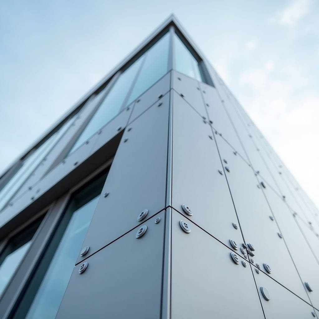
When a project specification calls for aluminum soffit panels on a high-rise commercial façade, the conversation rarely starts with the panel itself. It starts with the gap—the 20mm, 30mm, or 50mm open joint between panels that nobody sees but every façade engineer loses sleep over. Open-joint rainscreen soffits are deceptively simple in appearance and brutally unforgiving in execution. Get the joint width wrong by 3mm across a 200-meter elevation, and the cumulative visual drift becomes visible from street level. This is where shop-drawing discipline, thermal movement calculation, and installation sequencing converge into a single make-or-break detail. The following analysis unpacks the engineering logic behind open-joint aluminum soffit panel systems, from joint-width tolerance stacking to drainage plane continuity, written for contractors and specifiers who need the soffit to perform exactly as drawn—no excuses, no site-level improvisation.
The Open-Joint Soffit: Why the Gap Matters More Than the Panel
An open-joint system deliberately leaves a controlled gap between adjacent aluminum soffit panels. Unlike sealed or caulked joints, the open joint allows air to circulate behind the cladding, equalizing pressure and letting incidental moisture drain or evaporate. This is standard practice on ventilated rainscreen façades across North America, the Middle East, and Southeast Asia.
The engineering problem is deceptively straightforward: the joint must be wide enough to accommodate thermal expansion of the aluminum, yet narrow enough that the dark cavity behind it does not read as a black stripe from the viewing distance. A 2.0mm-thick solid aluminum panel with a 2,400mm length will expand approximately 2.5mm to 3.0mm under a 50°C temperature swing. If the design joint is 20mm, that expansion consumes roughly 15% of the gap. If the panel is installed at 5°C ambient and the joint is set at exactly 20mm, a 55°C summer day closes the gap to roughly 17mm—still visually acceptable. But if the installer drifts the joint to 17mm during cold-weather installation, the gap shrinks to 14mm in summer, and panel-to-panel contact becomes a real risk.
Field Note: On a 42-story mixed-use tower in Kuala Lumpur, the soffit contractor used 2.5mm solid aluminum panels with a 25mm nominal open joint. The shop drawings specified a ±1.5mm joint tolerance per panel edge. Cumulative drift across 14 panels exceeded 18mm by the eighth floor—the result of installers aligning each panel to the previous one rather than to a fixed reference line. The fix required removing and re-installing three bays of soffit. The lesson: open joints demand a surveyed grid, not sequential alignment.
Panel Thickness and Flatness: Why 2.0mm Is the Floor, Not the Ceiling
Solid aluminum soffit panels—not aluminum composite material (ACM)—are typically specified at 2.0mm, 2.5mm, or 3.0mm thickness. The choice is not arbitrary. A 2.0mm panel spanning 600mm between support rails will exhibit visible oil-canning (localized waviness) under certain light conditions, particularly with dark PVDF colors and low-angle sunlight. Moving to 2.5mm or 3.0mm significantly reduces this effect, though at a weight and cost premium.
For horizontal soffit applications where the panel is viewed from directly below, oil-canning is less forgiving than on vertical walls. The downward viewing angle catches every ripple. A specifier who accepts 2.0mm for a wall panel should reconsider for a soffit, especially if the panel dimensions exceed 600mm in the short direction and the finish is a dark solid color.
Fabricators like Futeng® have addressed this by standardizing 2.5mm as the minimum for soffit panels wider than 800mm, with 3.0mm recommended for any panel exceeding 1,200mm in the short dimension. The cost difference between 2.0mm and 2.5mm is roughly 8–12% on the material side, but the rework cost of replacing oil-canned panels post-installation dwarfs that premium.
Thermal Movement: Calculating the Gap Before You Draw the Panel
The coefficient of linear thermal expansion for aluminum alloy 3003 or 5052—the two most common grades for solid aluminum cladding panels—is approximately 23.6 × 10⁻⁶ /°C. The formula is simple:
ΔL = α × L × ΔT
Where ΔL is the change in length (mm), α is the thermal expansion coefficient, L is the panel length (mm), and ΔT is the expected temperature range (°C).
For a 3,000mm-long panel subjected to a 60°C temperature swing (from -10°C winter night to 50°C summer surface temperature on a dark-colored panel), the calculation yields:
ΔL = 23.6 × 10⁻⁶ × 3,000 × 60 = 4.25mm
This means each end of the panel moves approximately 2.1mm relative to its center. The open joint at each end must be at least 2.1mm wider than the minimum aesthetic tolerance. If the architect demands a 15mm visual joint, the structural joint must be no less than 17.1mm, and the shop drawing should call out 18mm to provide a safety margin.
What gets overlooked: the aluminum support rail expands too. A continuous aluminum T-rail or hat channel running behind the soffit will expand at the same rate. If the rail is rigidly fixed at both ends to a steel substructure (which expands at roughly half the rate of aluminum), the differential movement creates shear stress at the fixings. The solution is to specify slotted holes at one end of each rail segment, allowing the aluminum to move independently of the steel.
Drainage Plane Continuity: The Hidden Layer Behind the Soffit
An open-joint aluminum soffit panel system is not waterproof. It is a rain-screen. Water passes through the open joints, lands on a drainage plane behind the panels, and must be directed to the building exterior. On a vertical wall, gravity does the work. On a horizontal soffit, gravity works against you—water pools rather than drains.
The drainage plane behind a soffit must be sloped. A minimum 2% slope (1:50) is standard, but 3% is safer. The membrane or metal sheet behind the panels should be continuous, with lapped joints oriented in the direction of drainage. Penetrations for lighting, sprinklers, or speakers must be individually flashed and sealed—these are the points where soffit leaks originate on 90% of projects.
One approach that has gained traction in Southeast Asian high-rise projects is the use of a secondary aluminum drip tray system behind the soffit panels. Each tray spans two bays, collects water from the open joints above, and drains it to the vertical mullion lines where it can be directed outward. The added material cost is roughly USD 12–18 per square meter, but the elimination of post-occupancy leak remediation makes the ROI straightforward.
PVDF Coating on Soffits: The UV Exposure Nobody Talks About
Soffit panels on a building with deep overhangs receive less direct UV radiation than the south-facing vertical façade. But soffit panels on a cantilevered balcony or an open walkway canopy receive reflected UV from the ground, surrounding buildings, and low-angle morning/afternoon sun. The cumulative UV dose can exceed that of a vertical wall.
PVDF (polyvinylidene fluoride) coatings based on Kynar 500® or Hylar 5000® resin systems are the industry standard for architectural aluminum. The specification should call for a minimum 70% PVDF resin by weight in the color coat, applied as a three-coat system (primer, color coat, clear coat) with a total dry film thickness of 30–35 microns for standard colors and 40–45 microns for metallic or bright colors.
For soffit applications specifically, the clear coat matters. The clear topcoat contains the UV absorbers that protect the color coat. A two-coat system (primer + color coat) saves roughly USD 3–5 per square meter but sacrifices 5–8 years of color stability on exposed soffits. The specifier who approves a two-coat system for a budget-sensitive project should understand that the trade-off is not theoretical—it will show up as chalking and color fade within 8–10 years.
Panel Size, Weight, and Handling: The Logistics of Soffit Installation
Aluminum soffit panels are awkward to handle. Unlike wall panels that can be lifted vertically, soffit panels must be maneuvered overhead, often from scaffolding or mobile elevated work platforms. A 2.5mm-thick solid aluminum panel measuring 1,200mm × 2,400mm weighs approximately 19.5 kg. That is manageable for a two-person crew on a wall. Overhead, it becomes a safety and ergonomics challenge.
This is where panel sizing intersects with constructability. Breaking a large soffit into smaller panels adds joints and fabrication cost but reduces individual panel weight and makes installation faster and safer. The optimal panel size for overhead installation is typically 600mm × 1,200mm to 900mm × 1,800mm, keeping individual panel weight below 15 kg. This is not a material limitation—it is a site productivity decision.
For international projects shipped via FOB or CIF terms, panel size also dictates packaging. Standard plywood crates accommodate panels up to 1,500mm × 3,000mm. Panels exceeding these dimensions require custom crating, which adds USD 8–15 per square meter to the logistics cost. Protective interleaving with polyethylene foam sheets (minimum 2mm thickness) between panels is non-negotiable—PVDF finishes scratch easily, and a scratched soffit panel is visible from below in ways that a scratched wall panel at 20 meters is not.
Comparative Analysis: Open-Joint vs. Closed-Joint Soffit Systems
The choice between open-joint and closed-joint (caulked or gasketed) aluminum soffit panels is not aesthetic—it is a performance and maintenance decision. The table below summarizes the key engineering trade-offs.
| Performance Factor | Open-Joint System | Closed-Joint System |
|---|---|---|
| Pressure equalization | Inherent; cavity pressure equalizes with exterior | Requires dedicated vents; risk of pressurization failure |
| Moisture management | Water passes through; relies on rear drainage plane | Water stopped at joint; sealant failure = leak |
| Thermal movement accommodation | Joint width absorbs movement; no sealant stress | Sealant must stretch/compress; cyclic fatigue risk |
| Joint width tolerance sensitivity | High; ±1.5mm drift visible from below | Moderate; sealant masks minor width variation |
| Long-term maintenance | None; no sealant to replace | Sealant replacement every 15–20 years |
| Installed cost (materials + labor) | Lower; no sealant, faster installation | Higher; sealant material + application labor |
| Acoustic performance | Open joints transmit sound; NRC dependent on cavity | Closed joints provide modest sound attenuation |
| Fire safety (NFPA 285 / EN 13501) | Open joints allow cavity ventilation; fire-stopping at floor lines required | Closed joints limit cavity airflow; still requires fire-stopping |
The data points toward open-joint systems for most commercial soffit applications, provided the drainage plane is detailed correctly and the joint-width tolerance is enforced during installation. Closed-joint systems remain relevant for interior soffits, parking garage undersides where vehicle exhaust is a concern, and projects where the rear drainage plane cannot be sloped.
Fire Performance and Code Compliance at the Soffit Line
The intersection of a vertical façade and a horizontal soffit is a fire propagation path. The 2021 International Building Code (IBC) and NFPA 285 require that the entire exterior wall assembly—including the soffit—be tested as a system. Aluminum soffit panels with a polyethylene (PE) core would fail this test. Solid aluminum panels, being non-combustible (the aluminum itself is rated A1 per EN 13501-1), pass without issue.
However, the cavity behind the soffit requires fire-stopping at each floor line and at the intersection with the vertical façade. This is typically achieved with mineral wool fire barriers compressed into the cavity and held in place with steel angles. The detail must be coordinated between the soffit contractor, the vertical cladding contractor, and the fire-stopping subcontractor—three trades that rarely sit in the same coordination meeting.
The specification should reference ASTM E84 for surface burning characteristics and ASTM E119 for fire resistance of the assembly. For projects in the Middle East, the relevant standard is typically the UAE Fire and Life Safety Code of Practice, which aligns closely with NFPA requirements.
Shop Drawings: The Document That Prevents 80% of Site Problems
A well-executed aluminum soffit panel installation begins with shop drawings that answer every question before the first panel leaves the factory. The minimum information set for soffit shop drawings includes:
- Panel layout plan with individual panel numbering and dimensions
- Joint-width callouts at every panel edge, not just a generic note
- Fixing point locations with load calculations for each anchor type
- Thermal movement diagram showing expansion direction and fixed/sliding points
- Drainage plane layout with slope direction and lap-joint orientation
- Perimeter closure details at the interface with vertical cladding, parapets, and penetrations
- Lighting and MEP coordination drawings showing all cutouts and reinforcement
The shop drawing review process should involve the architect, the structural engineer, and the building envelope consultant. A common failure mode: the architect approves the panel layout for aesthetics, the structural engineer approves the fixing design for loads, but nobody checks whether the panel joint layout aligns with the drainage plane joints behind it. The result is a soffit that looks right on paper and leaks on site.
Procurement and Supply Chain: What the Lead Time Actually Looks Like
For a typical commercial project requiring 2,000–5,000 square meters of custom aluminum soffit panels, the supply chain timeline from order placement to site delivery runs as follows:
- Shop drawing preparation and approval: 3–4 weeks
- Material procurement (aluminum coil, PVDF coating): 2–3 weeks
- Fabrication (cutting, bending, routing, assembly): 4–6 weeks
- Quality control and packaging: 1 week
- Ocean freight (Asia to North America/Europe): 3–5 weeks
- Customs clearance and inland transport: 1–2 weeks
Total: 14–21 weeks from order to site. This timeline assumes no major design changes after shop drawing approval. A late-stage color change can add 3–4 weeks if the PVDF-coated coil must be re-ordered. Contractors who place the soffit panel order at the same time as the vertical cladding order—rather than treating it as an afterthought—avoid the schedule compression that leads to rushed fabrication and installation errors.
Futeng® and similar established fabricators maintain buffer stock of standard aluminum coil gauges and PVDF colors, which can compress the material procurement phase by 1–2 weeks for repeat colors. For custom RAL or Pantone-matched colors, the full procurement timeline applies.
Installation Sequencing: Why the Soffit Goes Last—and First
On a typical curtain wall project, the vertical cladding is installed first, followed by the soffit panels. This sequence makes sense structurally—the vertical panels provide the reference plane for the horizontal soffit. But it creates a logistical problem: the soffit contractor is working underneath completed vertical cladding, with limited access and a high risk of damaging finished surfaces.
An alternative sequence that has proven effective on several Southeast Asian high-rise projects: install the soffit support rails and drainage plane immediately after the structural slab is complete, before the vertical cladding begins. The soffit panels themselves are installed later, but the critical infrastructure is in place early. This approach requires close coordination with the vertical cladding contractor to ensure the soffit edge detail aligns with the vertical panel bottom edge, but it eliminates the access nightmare of working under a completed façade.
Pro Tip: When specifying soffit panel installation tolerances, reference AAMA 501.1 for field testing of metal curtain walls and ASTM E283 for air leakage. Even though an open-joint soffit is not an air barrier, the substructure and drainage plane behind it should be tested for air and water penetration before the panels are installed. Finding a leak in the drainage plane after the aluminum soffit panels are up is a five-figure mistake.
Frequently Asked Questions from the Field
What is the minimum recommended thickness for aluminum soffit panels on exterior applications?
For exterior soffits, 2.0mm is the absolute minimum for solid aluminum panels, but 2.5mm is strongly recommended for any panel exceeding 600mm in the short dimension. Panels larger than 1,200mm should use 3.0mm to minimize oil-canning. These recommendations apply to solid aluminum panels (alloy 3003 or 5052), not aluminum composite panels.
How do open-joint aluminum soffit panels handle wind uplift?
Open-joint systems equalize pressure across the panel face, reducing net wind load compared to sealed systems. However, the panel fixings must still resist the localized pressure on each panel. The design wind load is calculated per ASCE 7 (US) or EN 1991-1-4 (Europe), and the fixing spacing is determined by the panel dimensions and the allowable deflection (typically L/175 for soffit panels).
Can aluminum soffit panels be installed directly onto a concrete slab soffit?
Yes, but not directly. A subframe system—typically aluminum hat channels or adjustable steel brackets—must be installed between the concrete and the panels to create the drainage cavity and allow for leveling. Direct-fixing aluminum panels to concrete without a cavity creates a trapped moisture condition that will corrode the panel fixings and stain the panel surface.
What PVDF coating specification is appropriate for coastal soffit applications?
For coastal environments (within 5km of saltwater), specify a three-coat PVDF system with a minimum 35-micron total dry film thickness, using a chrome-free pretreatment per AAMA 2605. The clear topcoat should contain UV stabilizers rated for high-humidity, high-salt-spray exposure. Some manufacturers offer a four-coat system with an additional corrosion-inhibiting primer for extreme marine environments.
How are aluminum soffit panels tested for color consistency across a large batch?
Color consistency is verified using a spectrophotometer, measuring Delta E (CIE Lab) values against the approved control sample. For architectural soffit panels, Delta E should not exceed 1.0 within a single batch and 1.5 between batches. Panels are typically checked at the factory before packaging, and a set of retained samples is held for site reference. This is particularly critical for metallic and mica finishes, where color shift is more noticeable than on solid colors.
The open-joint aluminum soffit panel system is a study in disciplined engineering rather than architectural expression. The panels themselves are simple—flat, folded, or perforated aluminum sheets with a PVDF finish. The complexity lives in the joints, the drainage plane, the thermal movement strategy, and the installation sequence. For the contractor and specifier, the difference between a soffit that performs for 25 years and one that generates callbacks within 12 months is not the panel brand or the coating warranty. It is the quality of the shop drawings, the rigor of the joint-width tolerance enforcement, and the continuity of the drainage plane behind the panels. Get those three right, and the aluminum soffit panels will do exactly what they are supposed to do: disappear into the building's shadow line and stay there.