Aluminum Facade Seismic Test Methods for Solid Aluminium Panel Interstorey Drift and Serviceability
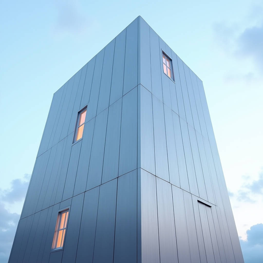
An Aluminum Facade Seismic Test is not a single pass-fail exercise but a staged protocol that measures how a solid aluminium cladding assembly behaves under interstorey drift, racking, and the low-intensity shaking that precedes visible damage. For contractors and procurement teams specifying 2.0 to 3.0 mm solid aluminium panels, the test answers one practical question: will the facade stay attached, stay weathertight, and remain serviceable after the building frame moves? The answer depends less on the panel itself and more on the connection geometry, the movement joint design, and the bracket stiffness that ties the panel back to the structure. This article walks through the test methods, the data you should demand from a supplier, and the engineering decisions that separate a facade that survives a seismic event from one that merely looks like it might.
Why Solid Aluminium Panels Change the Seismic Conversation
Solid aluminium cladding panels differ from other facade materials in a way that matters during a seismic event. The panel is a stiff, flat sheet with a defined thickness, typically 2.0, 2.5, or 3.0 mm, coated with a PVDF finish. Because the panel itself has no internal core, its mass is low and its flexural behaviour is predictable. That predictability is an advantage. A solid panel transmits movement through its brackets and joints in a way that can be modelled and tested with confidence.
The failure modes that appear in seismic testing of solid aluminium facades are rarely a rupture of the panel sheet. They are almost always connection failures. Bracket pull-out, fastener fatigue, gasket extrusion, and sealant tearing at movement joints account for the majority of serviceability losses observed in the field. The panel survives; the system fails. This is why an Aluminum Facade Seismic Test must be run on a full-scale mock-up that reproduces the actual connection details, not on a bare sheet in isolation.
The Interstorey Drift Problem
Interstorey drift is the relative horizontal displacement between two consecutive floor levels when the building sways. A typical design drift ratio for a high-rise in a moderate seismic zone is around 1/250 to 1/400 of the storey height. For a 3.6 m storey, that translates to roughly 9 to 14 mm of relative movement at the top of each panel. The facade must accommodate that movement without transferring load into the glass or the panel edges and without losing its weather seal.
For solid aluminium panels, the movement is absorbed at the joint between panels and at the bracket-to-structure interface. A rigidly fixed panel will crack its sealant and bend its brackets. A properly designed system allows controlled slip at the bracket and a flexible joint profile that can take the racking movement without tearing. The test mock-up must include these joints at full scale and at the exact spacing used on the project.
What a Proper Aluminum Facade Seismic Test Measures
A credible test protocol follows the sequence used in curtain wall laboratories and described in industry guidance such as the AAMA mock-up testing framework. The sequence matters because it reproduces real-world conditions. The facade is first tested for air infiltration, water leakage, and wind resistance at its design pressures. Then it is subjected to low-intensity seismic input on a shaking table or drift rig. After the seismic input, the air, water, and wind tests are repeated to measure post-earthquake serviceability.
This before-and-after comparison is the core of the test. A facade that passes its performance tests before the seismic event but fails them after has lost its serviceability, even if no panel fell. The AAMA mock-up guidance and the interstorey drift testing protocols referenced by testing bodies such as Intertek and Tecnalia all stress this dual evaluation.
Test Parameters You Should Specify
- Drift ratio: Specify the design interstorey drift ratio, typically 1/250 to 1/400, and the test drift, which is often 1.5 times the design value to build in margin.
- Racking: The mock-up must be racked in-plane to simulate the parallelogram deformation of the building frame, not just pushed laterally.
- Movement joint width: Record the joint width at rest and under maximum drift to verify the gasket and sealant can accommodate the movement.
- Cycles: Specify the number of low-intensity cycles, commonly 10 to 20, to simulate repeated aftershocks.
- Post-test performance: Require air, water, and structural retests after the seismic input, with acceptance criteria defined in advance.
These parameters are not optional extras. They are the difference between a certificate that proves nothing and a data package that lets your structural engineer sign off with confidence.
Connection Design That Passes the Test
The bracket is the component that decides whether a solid aluminium panel system passes an Aluminum Facade Seismic Test. A bracket that is too stiff transfers every millimetre of drift into the panel edge and the sealant. A bracket that is too loose allows the panel to rattle and lose its alignment. The right design uses a slotted hole or a friction connection that allows controlled slip in the drift direction while resisting wind suction perpendicular to the facade.
For a 2.5 mm solid panel, the bracket spacing is typically 400 to 600 mm along the panel edge. The bracket material is usually extruded aluminium or stainless steel, and the fasteners are stainless steel to avoid galvanic corrosion against the aluminium panel. The sealant at the movement joint is a low-modulus silicone that can stretch to 100 percent elongation without tearing, and the backing rod is sized to control the sealant depth-to-width ratio at roughly 1 to 2.
A Practical Data Table for Joint and Bracket Selection
| Panel Thickness | Bracket Spacing | Movement Joint Width | Sealant Type | Max Drift Capacity |
|---|---|---|---|---|
| 2.0 mm | 400 mm | 12 mm | Low-modulus silicone | ± 8 mm |
| 2.5 mm | 500 mm | 15 mm | Low-modulus silicone | ± 10 mm |
| 3.0 mm | 600 mm | 18 mm | Low-modulus silicone | ± 12 mm |
The table reflects typical engineering practice for solid aluminium panels in a moderate seismic zone with a 1/300 design drift ratio. The movement joint width is the critical number. If the joint is too narrow, the sealant cannot stretch far enough and it tears at the first significant aftershock. If it is too wide, the visual appearance suffers and the air and water performance at rest is harder to maintain. The values above balance those competing demands.
Post-Earthquake Serviceability and the Cost of Getting It Wrong
The most expensive failure in a seismic event is not a panel that falls. It is a facade that looks intact but leaks air and water, forcing a full re-seal of the building envelope while tenants are already displaced. The post-test air and water retests in an Aluminum Facade Seismic Test are designed to catch exactly this scenario. A system that passes the retests can be re-occupied with minimal intervention. A system that fails them requires a scaffold, a re-seal, and a schedule delay measured in weeks.
For a typical 10,000 m² facade, the cost of a full re-seal after a seismic event can run to several hundred thousand dollars when access, labour, and lost occupancy are included. The cost of running a proper full-scale seismic mock-up test on a representative 6 m by 4 m section is a fraction of that figure. The economic argument for testing is not theoretical. It is a direct comparison between a controlled laboratory cost and an uncontrolled field remediation cost.
What to Demand From a Solid Aluminium Panel Supplier
When you evaluate a supplier for a project in a seismic zone, ask for the test data that supports their system, not just a material certificate. A credible supplier should provide full-scale mock-up test reports showing the drift ratio achieved, the post-test serviceability results, and the connection details used in the test. They should also provide the panel thickness options, the PVDF coating specification, and the bracket and sealant recommendations that match the tested assembly.
Futeng® supplies solid aluminium cladding panels in 2.0, 2.5, and 3.0 mm thicknesses with a PVDF finish, and works with facade contractors to match the tested connection geometry to the project drawings. The point is not the brand. The point is that the supplier should be able to connect their material specification to a tested assembly, so your engineer does not have to guess whether the panel you bought will behave like the panel that was tested.
Standards and References That Anchor the Test
The test methods and performance criteria for facade seismic behaviour are anchored in a set of recognised standards and industry references. The ISO suite of facade testing standards covers air, water, and structural performance. The ASTM standards for curtain wall testing, including structural performance under wind load, provide the baseline for the pre- and post-seismic tests. The AAMA mock-up guidance and the European EN 13050 dynamic watertightness standard round out the reference set for a complete evaluation.
For the seismic input itself, the design drift ratio and the building response are typically derived from the local building code, which in many jurisdictions references the seismic provisions of the International Building Code. The aluminium structure design follows the Specification for Aluminum Structures, which governs the allowable stresses in the extruded brackets and the panel-to-bracket connections. Specifying these references in your project documents gives the testing laboratory an unambiguous basis for the acceptance criteria.
Engineering Recommendations for Your Next Project
Three decisions will determine whether your solid aluminium facade passes an Aluminum Facade Seismic Test and, more importantly, whether it serves the building after the shaking stops. First, specify the drift ratio and the test drift explicitly in the performance specification, and require a full-scale mock-up test that reproduces the actual connection details. Second, design the movement joints with enough width to accommodate the drift without tearing the sealant, using the panel thickness and bracket spacing as the starting point for the joint dimension. Third, select the bracket and sealant system as a matched assembly, not as separate components, so the tested behaviour reflects what is installed on site.
None of these decisions is exotic. They are the standard engineering practice for facades in seismic zones, applied with discipline. The cost of skipping the mock-up test is a facade that looks correct on paper and fails in the field. The cost of running it is a small line item that buys certainty about the most safety-critical and serviceability-critical component of the building envelope. For a solid aluminium panel system, that certainty is worth the test.