How Aluminum Alloy Yield Strength Controls Solid Cladding Panel Flatness and Wind Load Performance
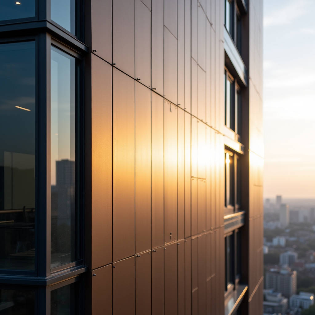
When a facade panel spans between floor slabs on a 40-story tower, the only thing standing between a flat, precise building envelope and a visibly wavy, oil-canning mess is the aluminum alloy yield strength of the skin material. Yield strength is not an abstract number on a mill test report. It is the stress threshold at which a solid aluminum cladding panel transitions from elastic deformation—where it springs back to flat—to plastic deformation, where the bend, ripple, or dent becomes permanent. For architects and facade contractors specifying 2.0mm, 2.5mm, or 3.0mm solid aluminum sheets, understanding this threshold means the difference between a facade that reads as crisp and monolithic versus one that catches light in all the wrong ways. This article examines how aluminum alloy yield strength directly governs panel flatness, wind load resistance, and long-term dimensional stability in solid aluminum cladding applications, with practical engineering guidance for specification writers and project managers.
What Yield Strength Actually Means for a Cladding Panel
Yield strength is the stress level, measured in megapascals (MPa) or kilopounds per square inch (ksi), at which a metal stops behaving elastically and starts deforming plastically. Below this threshold, remove the load and the aluminum returns to its original geometry. Exceed it, and the panel permanently changes shape. For solid aluminum cladding panels, this is not a theoretical concern. A 1.5-meter by 3-meter panel of 2.5mm thickness subjected to wind suction cycles that push stress beyond the yield point will gradually accumulate permanent set—a subtle but irreversible curvature that destroys the visual flatness of the facade.
The distinction between yield strength and ultimate tensile strength matters here. Ultimate tensile strength tells you when the material fractures. Yield strength tells you when it stops being flat. In cladding, fracture is rare; permanent deformation is the daily adversary. A panel that has yielded does not need to crack to fail the architectural intent. The 0.2% offset yield strength—the standard metric reported on mill certificates per ASTM B209 for aluminum sheet—defines the stress that produces 0.2% permanent strain. This is the number that facade engineers should be pulling from material data sheets, not the ultimate tensile figure.
For context, pure aluminum (1100-O) yields at roughly 34 MPa. That is barely 5 ksi. A 6061-T6 panel yields at approximately 276 MPa (40 ksi). That is an eightfold difference from the same base metal, achieved entirely through alloying and heat treatment. The implication for cladding specification is straightforward: alloy and temper selection is not a metallurgical footnote; it is the primary determinant of whether a panel stays flat under service loads.
Alloy Series and Temper: The Two Variables That Control Everything
The aluminum alloy yield strength of any given sheet is controlled by two factors: the alloy series—which dictates the primary alloying elements—and the temper designation, which describes the thermal and mechanical processing history. These two variables interact in ways that directly affect cladding performance.
5xxx Series: Magnesium-Strengthened, Work-Hardened
The 5xxx series, with magnesium as the primary alloying element, is the workhorse of architectural cladding in coastal and high-humidity environments. Alloys like 5052-H32 and 5754-H22 offer yield strengths in the range of 130 to 195 MPa, depending on the temper. These alloys are not heat-treatable; their strength comes from cold work and solid-solution strengthening. The H32 temper, for instance, indicates strain-hardened and then stabilized through a low-temperature thermal treatment. This stabilization is critical for cladding because it reduces the risk of stress-corrosion cracking in service.
5052-H32 delivers a typical yield strength of 193 MPa (28 ksi) with excellent corrosion resistance in marine atmospheres. For projects within 5 kilometers of saltwater, this alloy is frequently the default choice. The trade-off is formability: 5xxx alloys work-harden rapidly during bending, which means fabricators must account for springback when forming panel returns and stiffener profiles. A 5052-H32 panel bent to 90 degrees will spring back more than a 6061-T4 panel, requiring over-bending compensation in the brake press setup.
6xxx Series: Heat-Treatable, Higher Strength
The 6xxx series, alloyed with magnesium and silicon, is heat-treatable and offers higher yield strength potential. 6061-T6, the most common architectural alloy in this series, achieves a yield strength of approximately 276 MPa (40 ksi). This is roughly 43% higher than 5052-H32. For projects where panel spans are large, wind loads are high, or the architect demands minimal stiffener reinforcement, 6061-T6 provides a measurable advantage.
However, the 6xxx series carries a corrosion resistance penalty compared to 5xxx. In coastal environments, 6061-T6 panels require a robust PVDF coating system—typically a three-coat or four-coat system with a minimum total dry film thickness of 30 microns per AAMA 2605—to prevent filiform corrosion at cut edges and fastener penetrations. The heat-affected zone from welding also reduces yield strength locally in 6xxx alloys, which means mechanically fastened or adhesive-bonded stiffener attachment methods are preferred over welded stiffeners for 6061-T6 panels.
3xxx Series: Moderate Strength, Maximum Formability
Alloys like 3003-H14 occupy a middle ground, with yield strength around 145 MPa (21 ksi). These are less common in high-end architectural cladding but appear in soffit panels, interior wall linings, and applications where complex forming—deep drawn panel profiles, curved elements, perforated screens—is more critical than maximum spanning capability. The lower yield strength of 3003-H14 means closer stiffener spacing or thicker gauge material to achieve the same flatness standard as a 5052 or 6061 panel.
Wind Load, Span, and the Yield-Limited Design Approach
The relationship between aluminum alloy yield strength and panel design is governed by the allowable stress design methodology codified in the Aluminum Design Manual published by the Aluminum Association. For cladding panels subjected to wind load, the controlling limit state is typically not ultimate strength but serviceability: deflection under load and permanent set after load removal.
A solid aluminum panel spanning between horizontal girts or vertical mullions behaves as a thin plate under uniform lateral pressure. The maximum bending stress at the center of the panel, for a simply supported rectangular plate, can be estimated using plate theory coefficients. For a panel with aspect ratio a/b (long side/short side), the maximum bending moment per unit width is:
M = β · q · b²
Where β is a coefficient from plate theory (typically 0.10 to 0.12 for common aspect ratios), q is the uniform wind pressure, and b is the short span dimension. The resulting bending stress is:
σ = 6M / t²
Where t is the panel thickness. The design criterion is that this stress must remain below the allowable stress, which is typically the yield strength divided by a safety factor of 1.65 for buildings per the Aluminum Design Manual.
Consider a practical example: a 2.5mm thick 5052-H32 panel (yield strength 193 MPa) spanning 600mm between supports, subjected to a design wind pressure of 2.0 kPa (typical for mid-rise buildings in moderate wind zones). The allowable stress is 193 / 1.65 = 117 MPa. For a square panel with β = 0.10, the bending stress works out to approximately 69 MPa—well within the allowable range. But increase the span to 900mm with the same thickness and pressure, and the stress jumps to roughly 155 MPa, exceeding the allowable limit. The panel would need to step up to 3.0mm thickness or switch to 6061-T6 to maintain compliance.
This is not an academic exercise. On a recent 25-story residential tower in a typhoon-prone region, the facade consultant specified 6061-T6 solid aluminum panels at 3.0mm thickness for the upper floors where design wind pressure exceeded 3.5 kPa. The lower floors, with design pressure of 1.8 kPa, used 5052-H32 at 2.5mm. The alloy switch saved approximately 15% in material cost on the lower portion while maintaining identical visual appearance after PVDF coating. Suppliers like Futeng® regularly provide mill test reports that verify the yield strength of each batch, allowing the design team to confirm that the material delivered matches the structural assumptions in the facade calculations.
Temperature Effects on Yield Strength: What Happens on a Hot Facade
A dark-colored PVDF-coated aluminum panel on a south-facing elevation in summer can reach surface temperatures of 80°C (176°F). At these temperatures, aluminum alloy yield strength does not remain constant. The reduction is alloy-dependent and non-trivial for design.
For 6061-T6, yield strength at 80°C drops to approximately 90% of its room-temperature value—from 276 MPa to roughly 248 MPa. For 5052-H32, the reduction is more pronounced: yield strength at 80°C falls to approximately 82% of ambient, from 193 MPa to about 158 MPa. This temperature-dependent strength reduction is documented in the Aluminum Association's Aluminum Design Manual and in MIL-HDBK-5J. For projects in hot climates—the Middle East, Southeast Asia, northern Australia—this derating must be factored into the allowable stress calculation. A panel that is just adequate at 20°C may be under-designed at 70°C.
The practical implication is that dark-colored panels (low solar reflectance index) in hot climates should either use a higher-strength alloy, a thicker gauge, or closer stiffener spacing to compensate for the elevated-temperature yield strength reduction. A 5052-H32 panel at 2.5mm that works for a white or light-gray finish may need to be upgraded to 3.0mm for a black or dark bronze finish on the same building elevation, purely due to the thermal derating effect.
Stiffener Design and the Yield Strength Connection
Solid aluminum cladding panels are rarely flat plates without reinforcement. Stiffeners—typically aluminum extrusions or formed profiles bonded or mechanically attached to the panel back—increase the effective section modulus and reduce the unsupported span. The yield strength of both the panel skin and the stiffener material must be considered together.
A common stiffener configuration uses a 6063-T5 extruded hat section, which has a yield strength of approximately 145 MPa. If this stiffener is bonded to a 5052-H32 panel skin (193 MPa yield), the composite section has a hybrid yield behavior. The lower yield strength of the stiffener may govern the overall section capacity if the stiffener flange is in compression. For this reason, many fabricators prefer 6061-T6 extruded stiffeners (241 MPa yield in extrusion form) when paired with 5052-H32 or 6061-T6 panel skins, ensuring that the stiffener does not become the weak link.
The attachment method also interacts with yield strength. Mechanically fastened stiffeners using stainless steel rivets create discrete load transfer points. The bearing stress at the rivet hole in the aluminum panel must be checked against the panel's yield strength. For a 2.5mm 5052-H32 panel with a 4.8mm diameter rivet, the bearing allowable is typically 1.5 times the tensile yield strength, or approximately 290 MPa. This is generally adequate, but in high-wind zones, the rivet spacing may need to be reduced to distribute bearing loads more evenly.
Structural adhesive bonding of stiffeners—using two-part epoxy or polyurethane adhesives—distributes stress continuously along the bond line, eliminating the stress concentrations at mechanical fasteners. However, the adhesive's shear strength and long-term durability under thermal cycling and moisture exposure must be validated. The bond line becomes the critical load path, and its performance is independent of the aluminum alloy yield strength on either side of the joint.
Comparative Yield Strength Data for Cladding-Relevant Alloys
The following table summarizes yield strength values for aluminum alloys commonly encountered in solid cladding panel specification. Values are typical for sheet product forms per ASTM B209. Actual values may vary by mill source and specific processing parameters.
| Alloy & Temper | Yield Strength (MPa) | Yield Strength (ksi) | Corrosion Resistance | Typical Cladding Application |
|---|---|---|---|---|
| 1100-H14 | 117 | 17 | Excellent | Interior linings, low-stress soffits |
| 3003-H14 | 145 | 21 | Excellent | Formed panels, curved cladding |
| 5005-H34 | 138 | 20 | Excellent | Anodized architectural sheet |
| 5052-H32 | 193 | 28 | Excellent (marine) | Coastal facade panels, high-humidity zones |
| 5754-H22 | 180 | 26 | Excellent | European-standard marine cladding |
| 6061-T4 | 145 | 21 | Good | Formed before aging; complex shapes |
| 6061-T6 | 276 | 40 | Good | High-wind zones, large spans, tall buildings |
| 6063-T5 | 145 | 21 | Good | Extruded stiffeners, trim components |
| 7075-T6 | 503 | 73 | Poor (stress corrosion) | Rarely used in architectural cladding |
7075-T6 is included for reference because it represents the upper bound of aluminum alloy yield strength in commercially available sheet, but its poor corrosion resistance and susceptibility to stress-corrosion cracking make it unsuitable for architectural cladding. The 2xxx series (2024-T3, etc.) is similarly excluded from cladding applications due to corrosion concerns.
Mill Certificates, Batch Variation, and What to Check
Specifying an alloy and temper on a drawing is necessary but not sufficient. The aluminum alloy yield strength of the material delivered to the fabrication shop must be verified against the specification. Mill test certificates (MTCs), also called mill test reports (MTRs), provide the actual measured mechanical properties for each production batch.
A proper MTC for aluminum sheet per EN 10204 Type 3.1 or ASTM B209 should include: alloy and temper designation, heat or lot number, product thickness, yield strength (0.2% offset), ultimate tensile strength, elongation percentage, and the test standard used. For cladding projects, the yield strength value on the MTC should be checked against the design assumption. A batch of 5052-H32 that tests at 175 MPa instead of the typical 193 MPa is still within the ASTM B209 specification minimum (which is 159 MPa for 5052-H32), but it is 9% below the value used in the facade engineer's calculations. If the design was tight, this batch could produce panels that are under-strength for the application.
This is why experienced facade contractors and suppliers like Futeng® maintain incoming material inspection protocols that verify MTC values before releasing material to production. For critical projects—high-rise towers, buildings in hurricane zones, or projects with large panel spans—some specifications require that the yield strength on the MTC exceed a project-specific minimum that may be higher than the ASTM minimum. This is a legitimate and prudent specification practice.
Fabrication Effects: How Bending and Cutting Change Yield Strength
The aluminum alloy yield strength of a flat sheet is not the same as the yield strength of the formed panel. Cold working during bending, punching, and routing locally increases yield strength through work hardening while reducing ductility. This is most pronounced in 5xxx alloys, which work-harden rapidly.
A 5052-H32 panel that is brake-formed to create a 25mm return leg will have a higher yield strength in the bend zone than in the flat field of the panel. The bend radius, typically specified as 1.5t to 2t (where t is material thickness) for 5052-H32, controls the severity of cold work. A tighter bend radius produces more work hardening and a higher risk of micro-cracking at the outer fiber of the bend. For 6061-T6, the minimum bend radius is larger—typically 2.5t to 3t—due to the lower ductility of the T6 temper. If tighter bends are required, 6061-T4 (solution heat-treated and naturally aged) can be formed and then artificially aged to T6 after forming, though this adds process complexity and cost.
Laser or waterjet cutting introduces a heat-affected zone (HAZ) at the cut edge. For 6xxx alloys, the HAZ experiences local annealing that reduces yield strength in a narrow band adjacent to the cut. For 5xxx alloys, the effect is less pronounced because these alloys are not heat-treatable. The HAZ width is typically less than 1mm for laser cutting of 2.5mm sheet, which is generally negligible for cladding applications. However, for panels with extensive cutouts or perforations, the cumulative effect of HAZ softening should be considered, particularly if the perforated panel is in a high-stress zone.
Coating Cure Cycles and Yield Strength
PVDF coating systems require a peak metal temperature of approximately 240°C to 250°C during the curing process. This temperature exposure can affect the aluminum alloy yield strength of heat-treatable alloys. For 6061-T6, the T6 temper is achieved by solution heat treatment at approximately 530°C followed by artificial aging at 160°C to 180°C. The PVDF cure cycle at 240°C to 250°C is above the artificial aging temperature but well below the solution heat treatment temperature. The result is a modest degree of over-aging, which can reduce yield strength by 3% to 5% compared to the as-received T6 condition.
For 5xxx alloys, the PVDF cure temperature is below the annealing temperature, and the H32 temper (strain-hardened and stabilized) is specifically designed to resist softening during moderate thermal exposure. The yield strength reduction for 5052-H32 after a typical PVDF cure cycle is generally less than 2%. This is another reason why 5xxx alloys are favored for architectural cladding: their mechanical properties are more stable through the coating process.
Specifications that require post-coating mechanical property verification should be aware that the relevant standard is the Aluminum Association's Aluminum Standards and Data, which references properties in the as-fabricated condition. If post-coating testing is required, the acceptance criteria should account for the small but real strength reduction caused by the coating cure cycle.
Designing for Seismic Drift and Yield Strength Interaction
In seismic zones, cladding panels must accommodate inter-story drift without losing attachment integrity or developing permanent deformation. The aluminum alloy yield strength of the panel and its connection system determines how much drift the system can absorb elastically.
Typical inter-story drift limits under the design earthquake are 1.5% to 2.5% of story height, depending on the building code and structural system. For a 4-meter story height, 2% drift equals 80mm of relative horizontal displacement. The cladding panel connections must accommodate this movement through a combination of elastic deformation of the panel itself, slotted connections, and deformation of the supporting subframe.
A solid aluminum panel that is rigidly fixed at all four corners will be forced to deform in-plane as the building frame displaces. The in-plane stiffness of a 2.5mm thick panel is high, and the resulting stresses can exceed yield strength at relatively small displacements. This is why seismic-compatible cladding systems use a combination of fixed points and sliding connections. The fixed point (typically at the top center of the panel) transfers gravity load, while the sliding connections at other locations allow differential movement. The yield strength of the panel at the fixed point connection must be sufficient to resist the concentrated gravity load plus any prying action from the sliding connections.
For projects in high-seismic regions—Japan, Chile, western North America, New Zealand—the panel alloy selection should consider not just wind load but also the seismic load path. 6061-T6 panels with higher yield strength provide greater margin against localized yielding at connection points during a seismic event.
Corrosion, Yield Strength, and the Long-Term Picture
Yield strength data on mill certificates represents the as-manufactured condition. Over a 30-year service life, corrosion can reduce the effective cross-section of a panel, which increases the stress in the remaining material under the same load. This is not a reduction in the material's yield strength per se, but a reduction in the load-carrying capacity that has the same practical effect.
For 5052-H32 panels in a marine environment with a properly applied PVDF coating system, corrosion loss is negligible over the design life. The Aluminum Association publishes atmospheric corrosion data showing that aluminum alloys in marine environments typically lose less than 0.025mm of thickness per decade. For a 2.5mm panel, that is a 1% section loss over 30 years, which is within the margin of the safety factor.
However, if the coating is damaged—by impact, poor installation, or inadequate edge coverage—localized pitting corrosion can occur. The stress concentration at a corrosion pit can initiate cracking at stress levels well below the nominal yield strength. This is why the AAMA 2605 specification for high-performance organic coatings on aluminum extrusions and panels is not just about color retention; it is a structural durability requirement. The coating protects the substrate, and the substrate's yield strength is only available if the substrate remains intact.
Practical Specification Guidance for Project Teams
Based on the relationships between aluminum alloy yield strength and cladding performance discussed above, the following guidance is offered for specification writers, facade engineers, and procurement managers:
For inland projects with moderate wind loads (design pressure below 2.0 kPa) and panel spans under 800mm, 5052-H32 at 2.5mm thickness is generally adequate and cost-effective. The alloy's excellent corrosion resistance provides margin against environmental degradation, and its yield strength of 193 MPa provides sufficient capacity for the serviceability limit state.
For coastal projects (within 5km of saltwater), 5052-H32 or 5754-H22 remains the preferred choice, but the coating specification should be upgraded to a four-coat PVDF system per AAMA 2605 with a minimum total dry film thickness of 35 microns. The panel thickness may need to increase to 3.0mm if spans exceed 700mm due to the higher wind loads typical of coastal exposures.
For high-rise towers (above 100 meters), tall-building wind effects—including vortex shedding and increased suction at building corners—generate design pressures that can exceed 4.0 kPa. In these zones, 6061-T6 at 3.0mm thickness is the appropriate starting point. The higher yield strength of 276 MPa provides the necessary capacity, and the 3.0mm thickness provides additional bending stiffness that helps control deflection under peak gusts.
For hot climates with dark-colored panels, apply a temperature derating factor of 0.85 to the room-temperature yield strength when calculating allowable stress. This may push the design toward a thicker gauge or a higher-strength alloy. The American Architectural Manufacturers Association (AAMA) provides guidance on thermal effects in its curtain wall design manuals.
For seismic zones, ensure that the panel connection system includes adequate movement capacity. The panel's yield strength should be verified at the fixed connection point under the combined gravity and seismic load case. The ASTM International standards for aluminum sheet (ASTM B209) and the Aluminum Design Manual provide the material properties and design methodology.
Always require mill test certificates per EN 10204 Type 3.1 or equivalent, and review yield strength values against the project-specific design assumptions before releasing material to fabrication. A batch that meets the ASTM minimum but falls below the design value can create a latent deficiency that may not become apparent until panels are installed and subjected to service loads.
The yield strength of aluminum alloy cladding panels is not a single number to be copied from a data sheet. It is a property that interacts with alloy chemistry, temper, temperature, fabrication processes, coating cycles, and connection design. Understanding these interactions allows project teams to specify with confidence, knowing that the panels will remain flat, stable, and visually precise for decades.