Aluminum Corner Trim Engineering for Solid Aluminium Cladding Facades
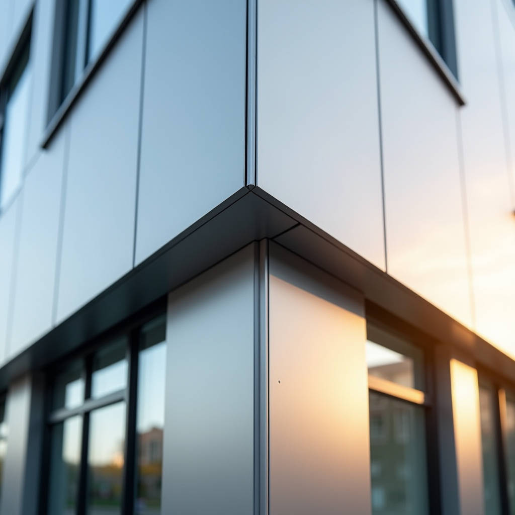
When a cladding contractor calls three weeks after handover about corner joint separation on a 12-story mixed-use facade, the conversation rarely starts with product specs. It starts with liability. Aluminum Corner Trim in solid aluminium cladding systems carries a disproportionate share of this exposure — corner profiles represent less than 5% of total linear meterage on most curtain wall projects, yet they account for a wildly outsized percentage of post-installation callbacks. The reasons are structural, thermal, and often entirely predictable. This article examines the engineering realities behind corner trim failure in solid aluminium panel facades, focusing on the intersection of alloy selection, fabrication tolerances, and on-site coordination that determines whether a corner detail survives its first decade or becomes a warranty claim.
Why Corner Details Fail Before the Panel Face Does
Flat panel faces have an easy life by comparison. They expand and contract in two dimensions with minimal constraint. A corner trim profile, by contrast, sits at the geometric intersection of two thermal movement vectors. When a 3.0mm solid aluminium panel on a south-facing elevation hits 70°C surface temperature in July, the corner trim absorbs differential movement from both adjoining planes simultaneously. The math is straightforward but often ignored during shop drawing review.
A 3-meter panel length in 6063-T6 alloy with a coefficient of thermal expansion of 23.4 × 10⁻⁶ /°C, subjected to a 50°C temperature swing, produces approximately 3.5mm of linear movement. At an outside corner, two panels meeting at 90 degrees each contribute this movement to the trim profile. The trim must accommodate roughly 5mm of combined differential displacement without buckling, fastener shear, or sealant adhesion loss. Profiles specified at 1.2mm wall thickness — common in residential-grade extruded trims — simply do not have the section modulus to handle this cyclic loading over multiple seasons.
ASTM B221 governs dimensional tolerances for aluminium extruded bars, rods, wire, profiles, and tubes. For corner trim applications in cladding, the twist tolerance for a 50mm leg profile is ±0.5° per 300mm of length — a spec that matters when cumulative twist across a 3-meter trim creates visible misalignment at the next floor line.
Alloy Selection Is Not Trivial
Procurement teams frequently treat corner trim as a commodity extrusion item. The specification sheet might say "aluminium corner trim" and stop there. The alloy matters enormously, and the wrong choice cascades into fabrication problems downstream.
6063-T5 is the default for many extruders. It extrudes easily, costs less, and provides adequate strength for interior applications. For exterior solid aluminium cladding corner trim, the conversation should start at 6063-T6 or 6061-T6. The difference in yield strength — 145 MPa for 6063-T5 versus 170 MPa for 6063-T6 and 240 MPa for 6061-T6 — translates directly into dent resistance at building corners where impact from maintenance equipment, wind-blown debris, and pedestrian traffic concentrates.
A 2.0mm wall thickness in 6063-T5 might meet the static load calculation on paper. After 18 months of thermal cycling, the same profile shows micro-yielding at fastener holes that no sealant bead can compensate for. The specifier who approved that substitution saved approximately $0.40 per linear meter on the extrusion and created a $40,000 remediation problem.
Alloy Performance Comparison for Corner Trim Applications
| Property | 6063-T5 | 6063-T6 | 6061-T6 | Relevance to Corner Trim |
|---|---|---|---|---|
| Yield Strength (MPa) | 145 | 170 | 240 | Dent resistance at high-traffic corners |
| Tensile Strength (MPa) | 185 | 215 | 290 | Fastener pull-through resistance |
| Elongation (%) | 12 | 12 | 10 | Formability for brake-pressed corner profiles |
| Thermal Expansion (×10⁻⁶/°C) | 23.4 | 23.4 | 23.6 | Joint design gap calculation |
| Anodizing Response | Excellent | Good | Fair | Finish consistency on visible corner elements |
| Relative Extrusion Cost | 1.0x | 1.05x | 1.15x | Budget impact on large-scale facade projects |
Fabrication Tolerances That Compound on Site
Solid aluminium corner trim comes from two fabrication paths: extruded profiles cut to length and mitered, or brake-pressed from flat sheet. Each path carries distinct tolerance accumulation risks that reveal themselves during installation.
Extruded corner trims typically ship in 6-meter lengths. The fabricator cuts and miters them to match panel dimensions. A ±1mm cut tolerance on each end of a 1.2-meter trim piece seems manageable. Stack that across 40 corner pieces on a single elevation, and the cumulative error reaches 80mm — enough to throw off the last panel's alignment by a visible margin. The fix usually involves field cutting, which removes the factory-applied PVDF coating edge protection and creates a corrosion initiation point.
Brake-pressed corner profiles from 2.5mm or 3.0mm solid aluminium sheet avoid the extrusion die cost but introduce springback variability. 6061-T6 sheet bent to 90 degrees will spring back between 2 and 4 degrees depending on grain direction, tooling condition, and batch temper. A fabricator who does not compensate for springback in the bending program produces corner trim that sits at 88 degrees instead of 90 — a 2-degree error that opens a 3.5mm gap at the trim-to-panel interface over a 100mm leg length. Sealant manufacturers specify maximum joint movement capability of ±25% for high-performance silicones. A 3.5mm gap on a nominal 6mm joint already exceeds this before any thermal movement occurs.
PVDF Coating on Corner Geometry: The Adhesion Challenge
Flat panel surfaces receive PVDF coating with predictable film build. The spray gun travels perpendicular to the surface, depositing 30-35 microns of Kynar 500®-based coating evenly. Corner trim profiles break this geometry. The inside radius of an L-shaped corner trim creates a shadow zone where electrostatic spray deposition drops below 20 microns. The outside corner edge, conversely, can build beyond 45 microns, creating a brittle thick edge prone to chipping during handling.
The AAMA 2605 standard for high-performance organic coatings on aluminium extrusions and panels specifies minimum dry film thickness of 30 microns on significant surfaces. The definition of "significant surface" becomes the point of contention. A corner trim's inside radius is visible from certain viewing angles but hidden from others. The coating applicator and the specifier need to agree on whether that radius constitutes a significant surface before the first batch goes through the line.
Pretreatment on corner profiles also demands attention. Chromate conversion coating — the standard pretreatment for PVDF adhesion — relies on complete solution contact with the aluminium surface. An L-shaped profile nested tightly in a coating rack can trap pretreatment chemicals in the inside corner, causing uneven etching that manifests as adhesion failure six months into service. Rack design for corner trim coating is not a production detail to delegate to the line operator; it belongs in the quality plan.
Thermal Bridging at Corner Conditions
Solid aluminium has a thermal conductivity of approximately 160 W/m·K. When an aluminium corner trim profile spans continuously from the exterior cladding plane to the building's structural framing, it creates a linear thermal bridge that building envelope consultants increasingly flag during design review.
The energy code implications vary by jurisdiction. ASHRAE 90.1 and the IECC require continuous insulation for most commercial wall assemblies. A solid aluminium corner trim that penetrates the insulation layer — even if only through fastener connections — introduces a thermal anomaly that must be accounted for in the overall U-factor calculation. The practical solution is a thermal break between the corner trim and the structural substrate, typically a 6mm PVC or polyamide isolator strip. This adds roughly $3-5 per linear meter to the installed cost and eliminates a condensation risk that would otherwise show up as interior water staining at corner locations during cold weather.
Condensation at corner trim locations is particularly insidious because it often appears on the interior drywall surface rather than the exterior cladding, leading building operators to misdiagnose the problem as a plumbing leak or roof failure. The investigation typically takes months, during which the aluminium corner trim continues to condense moisture from interior air against its cold back surface.
Wind Load Concentration at Building Corners
Wind tunnel studies consistently show that negative pressure coefficients at building corners reach 2-3 times the values measured at mid-wall locations. ASCE 7 provides corner zone pressure coefficients for components and cladding design that reflect this reality. A corner trim profile that is adequate for the field zone may be undersized for corner zone pressures.
For a 30-meter-tall building in Exposure Category B with a basic wind speed of 45 m/s, the corner zone design pressure can exceed 2.5 kPa (negative). This translates to approximately 250 kg of uplift force per square meter acting on the corner trim assembly. The fastener spacing that works for the panel field — typically 300mm on center — may need to tighten to 200mm or 150mm at corner zones. The trim profile's section properties must resist this load without excessive deflection that opens the sealant joint.
Futeng® has supplied solid aluminium corner trim profiles for projects in typhoon-prone regions where corner zone pressures dictated 3.0mm wall thickness and 150mm fastener spacing, well beyond what a standard architectural specification would call for. The engineering justification came directly from the wind load calculation, not from a desire to over-specify.
Corner Zone Fastener Spacing Recommendations by Wind Load
| Design Wind Pressure (kPa) | Trim Wall Thickness (mm) | Fastener Spacing (mm O.C.) | Fastener Type | Applicable Standard |
|---|---|---|---|---|
| < 1.0 | 1.5 - 2.0 | 300 | #10 self-drilling, SS | ASCE 7, Zone 4 |
| 1.0 - 1.5 | 2.0 | 250 | #12 self-drilling, SS | ASCE 7, Zone 5 |
| 1.5 - 2.5 | 2.5 | 200 | #14 self-drilling, SS | ASCE 7, Corner Zone |
| 2.5 - 3.5 | 3.0 | 150 | M6 SS bolt + rivet nut | ASCE 7, Corner Zone |
| > 3.5 | 3.0+ | 125 | M8 SS bolt + rivet nut | Project-specific wind tunnel |
Sealant Joint Design at Corner Trim Interfaces
The sealant joint between a corner trim profile and the adjacent flat panel is the most weather-exposed joint in the entire cladding assembly. Rainwater driven by corner-accelerated wind strikes this joint at oblique angles. UV exposure is higher because the corner geometry receives direct sunlight from two azimuth angles during the day.
A properly designed corner trim joint specifies a backer rod to control sealant depth, a minimum 6mm joint width for medium-modulus silicone, and a depth-to-width ratio of 1:2 for optimum movement accommodation. The specification should call out ASTM C920 Class 50 sealant — meaning it can accommodate ±50% joint movement — rather than Class 25 products that cost less but fail earlier at dynamic corner joints.
The most common field error is omitting the backer rod and filling the joint solid. A completely filled joint cannot accommodate movement because the sealant bonds to three surfaces (both panel edges and the substrate behind). This three-sided adhesion condition guarantees cohesive failure within the sealant bead within the first full thermal cycle. The repair requires cutting out the entire joint and re-sealing — a labor cost that dwarfs the few cents saved on backer rod material.
Installation Sequencing and Trade Coordination
Corner trim installation sits at the intersection of multiple trades. The cladding contractor installs the trim. The waterproofing contractor's membrane termination often lands behind the trim. The window installer's perimeter sealant may overlap the trim edge. The sequence matters because each trade's work either protects or compromises the corner trim's long-term performance.
The correct sequence places corner trim installation after the weather-resistive barrier and before window perimeter sealing. This allows the trim to capture the barrier edge and provides a clean substrate for window sealant adhesion. Reversing the sequence — installing windows first, then fitting corner trim around them — creates a lap condition where water can track behind the trim and into the rough opening.
On a recent 20,000-square-meter office tower project, the cladding sub-contractor and the window installer spent three days in a coordination meeting arguing over 40mm of overlap at corner conditions. The resolution — a pre-installed aluminum corner trim with a 25mm return leg that the window installer could seal against — added $2.80 per linear meter to the trim cost and eliminated a water ingress risk that the building envelope consultant had flagged as high probability.
Quality Control Checkpoints for Incoming Corner Trim
Before corner trim leaves the fabricator's facility, a defined set of QC checks prevents field disputes. The project specification should enumerate these checks explicitly rather than relying on the fabricator's standard procedures.
Dimensional checks start with leg length — measured on both legs of an L-profile at three points along the length. A 50mm × 50mm profile with a ±0.5mm tolerance on each leg sounds reasonable until the shorter leg creates a 1mm step at the panel interface that catches light and draws the eye. Straightness tolerance per ASTM B221 — 0.5mm per 300mm of length — should be verified on a granite surface plate, not with a tape measure on the shop floor.
Coating thickness measurement requires a calibrated eddy-current gauge. Measurements should be taken on both legs, the outside corner radius, and the inside corner radius. The inside radius measurement location should be specified as 10mm from the apex to avoid the shadow zone where coating thickness naturally drops. If the inside radius reading falls below 25 microns, the batch should be rejected or accepted only with a written concession from the specifier.
Anodized corner trim requires a separate set of checks. Anodizing thickness per AAMA 611 Class I architectural anodizing should be a minimum of 18 microns. The corner profile's geometry creates current density variations during anodizing that can produce color non-uniformity between the flat leg surfaces and the corner radius. A color match tolerance of 5 Delta E units between the trim and the adjacent panel is achievable with proper racking but requires the anodizer to run test coupons before committing to production quantities.
Cost Drivers Beyond the Extrusion Price
Procurement managers who compare corner trim quotes solely on the extrusion price per meter are comparing the smallest cost component. The installed cost of aluminum corner trim breaks down into material, fabrication, finishing, and installation — with fabrication and finishing typically dominating the total.
A 50mm × 50mm × 2.5mm 6063-T6 extruded corner profile might cost $4.50 per linear meter as a mill-finish extrusion. PVDF coating adds $3.00-4.00 per meter. Miter cutting and fabrication add $2.50-3.50 per meter. Installation labor, including fastener and sealant, adds $8.00-12.00 per meter depending on access conditions and building height. The total installed cost runs $18.00-24.00 per linear meter, of which the raw extrusion represents only 20-25%.
This cost structure means that value engineering efforts focused on reducing the extrusion cost — thinner walls, cheaper alloy — produce negligible savings while introducing disproportionate risk. A 10% reduction in extrusion cost saves $0.45 per meter against a total installed cost of $20.00. That $0.45 saving evaporates the first time a crew spends an hour repairing a dented corner trim that a 6063-T6 profile would have survived.
Specifying Aluminum Corner Trim for International Projects
Projects sourced across borders add complexity. A specification written around ASTM standards may encounter a fabricator whose quality system is built on EN 755 for extrusions and EN 12206 for coating. The standards are not interchangeable, but they are reconcilable if the specifier understands the equivalencies.
EN 755-2 calls out dimensional tolerances for aluminium extrusions that are broadly similar to ASTM B221 but differ in specific tolerance bands for certain profile dimensions. EN 12206 for coil-coated aluminium specifies coating thickness and performance requirements that align with AAMA 2605 at the high-performance end. The specifier should include a standards equivalency table in the project specification rather than assuming the fabricator will interpret ASTM references correctly.
Shipping damage is another international consideration. Corner trim profiles are inherently vulnerable to bending and surface damage during container transport. Packaging specifications should call for individual profile wrapping with polyethylene film, bundled in quantities not exceeding 50 pieces, with corrugated cardboard separators between layers. A wooden crate with internal bracing is the minimum acceptable outer packaging for sea freight. The incremental packaging cost of $1.50-2.00 per meter is recoverable several times over through reduced rejection rates at the destination port.
When to Use Brake-Pressed vs. Extruded Corner Trim
Neither fabrication method is universally superior. The choice depends on project-specific factors that should be evaluated during the design development phase rather than left to the fabricator's discretion.
Extruded corner trim offers tighter dimensional control, consistent leg thickness, and a sharper outside corner radius — typically 1-2mm versus 3-5mm for brake-pressed profiles. This sharper radius reads as more precise on high-visibility architectural corners. Extrusion also allows complex profile geometries — drip grooves, sealant channels, and return legs — that are impractical to achieve with press braking.
Brake-pressed corner trim from solid aluminium sheet eliminates die costs ($2,000-5,000 per profile) and lead times (4-6 weeks for die fabrication). It makes economic sense for projects requiring less than 500 linear meters of a given profile or for custom corner angles that are not 90 degrees. The trade-off is the springback variability discussed earlier and a slightly softer outside corner radius.
For projects exceeding 1,000 linear meters of corner trim with standard 90-degree geometry, extrusion is almost always the lower total-cost option once die amortization is factored in. The die cost spread across 1,000 meters adds $2-5 per meter — easily offset by reduced fabrication labor and lower rejection rates.
The decision between these two methods should be documented in the project's basis-of-design narrative. A fabricator like Futeng® that maintains both extrusion capabilities and CNC press brakes can offer unbiased guidance on which path suits the specific project parameters, but the specifier should understand the trade-offs well enough to evaluate that guidance critically.
Practical Takeaways for the Specification Writer
Writing a corner trim specification that actually gets followed requires more than referencing ASTM B221 and AAMA 2605. The following points should be explicit in the specification document, not buried in general notes that nobody reads after the bid stage.
First, state the alloy and temper unequivocally. "Aluminium corner trim shall be 6063-T6 or 6061-T6 extruded profile, minimum 2.5mm wall thickness." The "or" gives the fabricator flexibility while setting a floor on mechanical properties. Second, define the coating inspection locations — include the inside corner radius measurement point. Third, specify the sealant joint geometry: width, depth, backer rod type, and the requirement for two-sided adhesion. Fourth, require a mock-up that includes at least one outside corner and one inside corner, subjected to the specified wind load test and water penetration test per ASTM E1105 before production quantities are fabricated.
The mock-up requirement alone eliminates a surprising number of problems. When the installer, the fabricator, and the building envelope consultant stand in front of a corner mock-up and discuss the joint alignment, the sealant adhesion, and the coating appearance, the ambiguities in the specification become visible and resolvable. Skipping the mock-up to save two weeks in the schedule is a false economy that the project team will regret when the first corner trim joint opens up during the warranty period.
Corner trim is a detail that demands disproportionate attention because it carries disproportionate risk. The engineering is straightforward. The alloy selection, the fabrication tolerance stack, the coating adhesion, the thermal movement accommodation, and the wind load resistance are all quantifiable with standard calculation methods. The failure mode is almost always a breakdown in the chain of communication between the specifier, the fabricator, and the installer — a breakdown that a well-written specification and a properly executed mock-up can prevent. For solid aluminium cladding systems, the corner trim is where the architectural intent meets the engineering reality, and getting that intersection right is what separates a facade that performs from one that generates callbacks.