Aluminum Panel Dimensional Check What Dimensions Actually Matter and How to Verify Them
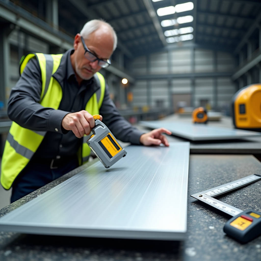
When a shipment of solid aluminium cladding panels arrives on site, the first question from the facade contractor is rarely about aesthetics. It is about whether the panels fit. An Aluminum Panel Dimensional Check is the single most consequential quality gate between factory release and installation. Panels that pass visual inspection but deviate by 2 mm in width or 1.5 mm in diagonal will cascade into rework costs that nobody budgeted for. This is not theoretical. On a mid-rise commercial tower with 4,000 panels, a systematic 1.5 mm over-width across the batch means the cumulative error at the final bay exceeds 60 mm — enough to blow the expansion joint tolerance and require field cutting on every panel in the last three floors. The dimensional check is where that problem gets caught before the crane lifts the crate.
Why Dimensional Accuracy Determines Facade Economics
Facade contractors operate on razor-thin margins. A typical unitised curtain wall installation runs at 12–18 panels per day per crew. When panels do not align with the support grid because of dimensional drift, that rate drops to 6–8 panels. The math is brutal. A crew costing $2,800 per day suddenly takes twice as long to cover the same area. Multiply that across a 20-week facade programme and the overrun reaches six figures. The root cause is almost always traceable to insufficient dimensional verification at the factory or at goods receipt.
Solid aluminium panels — 2.0 mm, 2.5 mm, and 3.0 mm gauge sheets formed into cassettes, trays, or hook-on panels — are fabricated through a sequence of shearing, punching, routing, bending, and welding. Each operation introduces potential deviation. A shear blade worn by 0.3 mm produces a consistent offset across thousands of panels. A press brake operator compensating for springback inconsistently creates angular variation that accumulates across the panel width. Without a structured Aluminum Panel Dimensional Check protocol, these errors remain invisible until installation.
The Critical Dimensions That Actually Matter
Not all dimensions carry equal weight. Over years of troubleshooting facade projects, the dimensions that consistently cause field failure are these:
1. Diagonal Difference (Squareness)
A panel that is perfectly sized but out of square by 2 mm will not seat into a precisely engineered subframe. The corners lift, the gaskets compress unevenly, and water ingress paths open. The industry tolerance for diagonal difference on panels up to 1,200 mm is ±1.5 mm per AAMA guidelines. Panels above 1,200 mm should hold ±2.0 mm. Measuring both diagonals with a calibrated steel tape and comparing the difference is the simplest and most revealing check.
2. Overall Width and Height
Overall dimensions are checked against the fabrication drawing, but the nuance is where you measure. A panel may measure correctly at the centre but be 1.2 mm over at the edges due to bowing introduced during welding. Three-point measurement — left, centre, right — catches this. The acceptable tolerance for panel overall dimensions is typically ±1.0 mm for panels under 1,000 mm and ±1.5 mm for panels 1,000–2,000 mm, referencing ASTM B209 as the baseline for aluminium sheet and plate tolerances before fabrication.
3. Fold Line Position and Bend Angle
On a cassette panel with return legs, the fold line position relative to the panel edge dictates how the panel sits in its carrier. A fold line offset by 1 mm changes the face plane by 1 mm. When adjacent panels share a shadow gap of 15 mm, that 1 mm shift is visible from 20 metres. Bend angles should be checked with a digital protractor. The standard tolerance is ±0.5° for 90° bends. Anything looser produces visible gap inconsistency.
4. Flatness (Oil Canning Resistance)
Flatness is a dimensional property that is often overlooked in formal checklists. A 2.5 mm solid aluminium panel spanning 1,200 mm × 3,000 mm should exhibit no more than 2 mm of deviation from a true plane per 300 mm of span when measured with a straightedge and feeler gauge. This is particularly critical for panels with PVDF coatings in dark colours, where thermal expansion exaggerates any waviness. The ISO 2768 general tolerance standard provides a useful reference framework for flatness tolerances on fabricated sheet metal components.
5. Hole and Slot Position
Mounting holes, drainage slots, and stiffener fixing points must be located within ±0.5 mm of nominal position. A hole pattern that drifts by 1 mm means the panel will not engage with its pre-installed brackets. On a rainscreen system with 8 fixing points per panel, cumulative misalignment forces the installer to elongate holes on site — voiding the corrosion protection at each enlarged hole.
Measurement Tools: What Actually Works on the Factory Floor
Sophisticated coordinate measuring machines (CMMs) and laser scanners exist, but the reality of most aluminium fabrication facilities is that dimensional checks are performed with handheld tools by quality inspectors working against production schedules. The tools that deliver reliable results are practical, not exotic:
- Calibrated steel tape measures (Class I accuracy, ±0.1 mm per metre) for overall dimensions. Fibreglass tapes are not acceptable — they stretch under tension and degrade with temperature.
- Digital callipers with 0.01 mm resolution for thickness verification and edge-to-hole measurements. Mitutoyo or equivalent grade.
- Digital protractors for bend angle verification. Magnetic base models allow hands-free reading on the press brake.
- Feeler gauge sets (0.05 mm to 1.0 mm range) paired with a precision straightedge for flatness checks.
- Surface plates (granite, Grade 0 or Grade 1) for checking smaller panels or critical reference faces.
- Go/No-Go gauges for hole diameters and slot widths. These are faster than callipers for high-volume checks and eliminate operator reading errors.
For larger panels exceeding 2,000 mm in any dimension, non-contact laser measurement systems become practical. Systems from manufacturers like ELOVIS combine length, width, and thickness measurement in a single pass, capturing data at production speed without panel contact. The investment threshold for such systems is approximately $45,000–$80,000, which is justifiable for facilities producing over 50,000 panels annually. For smaller operations, the handheld toolkit remains the standard.
Sampling Strategy: 100% Check vs. AQL-Based Inspection
The question every procurement manager asks: must every panel be checked? The answer depends on the panel's position in the facade and the consequence of failure.
For feature panels — those at building corners, entrance canopies, or areas where panels meet glazing with zero tolerance — 100% dimensional inspection is non-negotiable. A single out-of-tolerance panel in these locations stops the entire elevation.
For standard field-of-wall panels, an AQL (Acceptable Quality Limit) sampling plan per ISO 2859-1 is appropriate. A typical approach uses AQL 2.5 for major dimensions (overall width, height, diagonal) and AQL 4.0 for minor dimensions (hole positions, slot lengths). The sample size is determined by lot size. For a lot of 500 panels, the inspector checks 50 panels. If 3 or fewer fail major dimensional checks, the lot is accepted. If 4 or more fail, the lot is rejected or subject to 100% sorting at the supplier's cost.
This is not a theoretical exercise. On a recent project supplied by Futeng®, the AQL-based protocol caught a batch where the press brake backstop had drifted 0.8 mm over a production run of 300 panels. The 50-panel sample revealed 5 failures — exceeding the AQL 2.5 threshold. The entire batch was rechecked and 42 panels were reworked before shipping. The alternative would have been discovering the problem at installation, with panels already lifted to the 12th floor.
Common Dimensional Defects and Their Root Causes
| Defect | Typical Deviation | Root Cause | Detection Method | Prevention |
|---|---|---|---|---|
| Width oversize | +1.0 to +2.5 mm | Worn shear blade clearance | Tape measure, 3-point | Blade replacement every 50,000 cuts |
| Diagonal out of square | 1.5 to 4.0 mm difference | Inconsistent backgauge referencing | Diagonal comparison | Pinned corner jig for bending |
| Bend angle drift | ±1.0° to ±2.5° | Springback compensation error | Digital protractor | Test bend per batch, adjust parameters |
| Hole position shift | ±0.8 to ±2.0 mm | CNC turret punch tool wear | Calliper from reference edge | Tool replacement schedule, first-off check |
| Flatness deviation | 2.0 to 5.0 mm per 300 mm | Welding heat distortion | Straightedge + feeler gauge | Staggered welding sequence, post-weld flattening |
| Thickness variation | ±0.05 to ±0.15 mm | Mill tolerance on raw sheet | Digital calliper,多点 | Incoming material check per ASTM B209 |
Thickness Tolerance: The Starting Point No One Checks
Before any fabrication begins, the raw aluminium sheet carries its own dimensional uncertainty. ASTM B209 defines thickness tolerances for aluminium sheet and plate. For a 2.5 mm nominal sheet in alloy 3003 or 5052, the tolerance is ±0.10 mm for widths up to 1,500 mm. A sheet arriving at 2.40 mm is within specification but represents a 4% reduction in cross-sectional area. That reduction affects the panel's bending stiffness, which is proportional to the cube of thickness. A 4% thickness reduction translates to roughly an 11.5% reduction in stiffness.
A proper Aluminum Panel Dimensional Check protocol therefore begins at goods-in, not at finished goods. Measure incoming sheet thickness at five points — four corners and centre — using a digital calliper or micrometer. Record the values against the mill certificate. Suppliers that skip this step are effectively blind to the mechanical properties of the panels they are fabricating.
Thermal Effects on Dimensional Measurement
Aluminium has a coefficient of thermal expansion of approximately 23 × 10⁻⁶ per °C. A 3,000 mm panel measured at 5°C in an unheated factory will be 0.69 mm shorter than the same panel measured at 15°C. At 35°C — common in Middle Eastern fabrication shops — the panel will measure 1.38 mm longer than at 15°C. These differences are within the tolerance band for many projects, but when combined with fabrication tolerances, they can push a panel outside specification.
The practical solution is to conduct dimensional checks in a temperature-controlled environment (20°C ± 3°C) or to apply a correction factor when measuring at non-standard temperatures. For panels longer than 2,000 mm destined for projects with tight joint tolerances, temperature compensation should be documented in the inspection report.
Documentation: The Inspection Report That Protects Everyone
A dimensional check without documentation is a rumour. The inspection report must capture:
- Panel identification (project, elevation, floor, panel reference number)
- Date, time, and ambient temperature at measurement
- Inspector name and signature
- Measuring equipment used, including calibration due date
- Nominal dimension, measured dimension, and deviation for each critical parameter
- Pass/fail judgement against the specified tolerance
- Photograph of the panel with measurement being taken (for dispute resolution)
This report serves three purposes. It provides the contractor with evidence that panels were checked before shipment. It gives the fabricator a quality record for continuous improvement. And in the event of a dispute, it is the document that determines whether the problem originated at the factory or on site.
Integrating Dimensional Check Into the Broader Quality Workflow
Dimensional verification does not exist in isolation. It sits between material certification and surface finish inspection. The logical sequence for a solid aluminium panel quality workflow is:
- Incoming material check: Verify alloy, temper, and thickness against the mill certificate. Check for visible defects on the raw sheet surface.
- First-off inspection: After programming the CNC punch or press brake, produce one panel and perform a full dimensional check. Approve the setup before batch production begins.
- In-process sampling: At intervals determined by production volume (typically every 50 panels or every 2 hours, whichever comes first), pull a panel for dimensional check. This catches tool wear and parameter drift before it affects the entire batch.
- Final inspection: After surface finishing (PVDF coating or anodising), perform the complete dimensional check on the AQL sample. Coating thickness should be measured concurrently, as PVDF build-up of 30–40 microns can affect hole clearances and panel fit.
- Pre-shipment audit: A final dimensional spot-check on crated panels, focusing on the dimensions most likely to shift during handling — typically flatness and diagonal squareness.
This workflow aligns with the principles of ISO 9001 quality management and provides the traceability that facade contractors and building owners increasingly demand.
When the Check Fails: Decision Framework
A failed dimensional check triggers a decision tree. The options are:
- Rework: If the deviation is correctable — an oversized panel can be trimmed, a bent panel can be flattened — rework is the preferred path. Rework must be followed by re-inspection and documented separately.
- Concession: If the panel is slightly out of tolerance but the deviation can be absorbed by the installation system (e.g., a slotted bracket allows 3 mm of adjustment), the contractor may grant a concession. This must be in writing and specific to identified panels.
- Reject: If the deviation exceeds the concession limit and rework is not feasible, the panel is rejected. The fabricator absorbs the cost of replacement, including any schedule impact.
The cost of rejection is asymmetric. A panel that costs $85 to fabricate may cost $1,200 to replace once installation delays, crane standby, and programme extension are factored in. This is the economic argument for rigorous dimensional checking at source.
Practical Tolerance Tables for Solid Aluminium Cladding Panels
The following tolerances represent a synthesis of ASTM B209, AAMA 611, and practical field experience with solid aluminium panels in the 2.0–3.0 mm thickness range. They are appropriate for architectural facade applications where panel joints are 15–20 mm and shadow gaps are specified.
| Dimension | Panel ≤ 1,000 mm | Panel 1,000–2,000 mm | Panel 2,000–3,500 mm | Measurement Tool |
|---|---|---|---|---|
| Overall width/height | ±1.0 mm | ±1.5 mm | ±2.0 mm | Class I steel tape |
| Diagonal difference | ≤1.5 mm | ≤2.0 mm | ≤3.0 mm | Class I steel tape |
| Bend angle (90°) | ±0.5° | ±0.5° | ±1.0° | Digital protractor |
| Flatness (per 300 mm) | ≤1.5 mm | ≤2.0 mm | ≤2.5 mm | Straightedge + feeler |
| Hole position | ±0.5 mm | ±0.5 mm | ±0.8 mm | Digital calliper |
| Fold line position | ±0.5 mm | ±0.8 mm | ±1.0 mm | Digital calliper |
These tolerances assume measurement at 20°C ± 3°C. For panels measured outside this range, apply a thermal correction of 0.023 mm per metre per °C deviation from 20°C.
Making Dimensional Check a Contractual Requirement
The most effective way to ensure dimensional quality is to embed it in the supply contract. A specification clause that states "panels shall be manufactured to the dimensions shown on approved fabrication drawings" is insufficient. It provides no verification mechanism and no consequences for non-compliance.
A robust specification includes:
- Reference to the tolerance table above or an equivalent project-specific table
- Requirement for documented first-off inspection before batch production
- AQL sampling plan with defined accept/reject criteria
- Requirement for inspection reports to accompany each shipment
- Right of the buyer or their representative to witness dimensional checks at the factory
- Cost allocation for sorting, rework, or replacement of non-conforming panels
Suppliers that resist these requirements are signalling that their quality systems may not withstand scrutiny. Suppliers that welcome them — and can demonstrate a track record of dimensional compliance — are the partners that keep facade projects on schedule and within budget.
The Aluminum Panel Dimensional Check is not a bureaucratic exercise. It is the difference between panels that click into place and panels that require a grinder, a file, and a lot of expensive site labour. For the contractor, it is insurance. For the fabricator, it is the evidence that the product left the factory right. For the architect, it is the guarantee that the facade will look like the rendering. The time invested in checking dimensions at the factory is returned tenfold in avoided site chaos.