High Rise Facade Panels Wind Load Engineering and Solid Aluminium Specification Guide
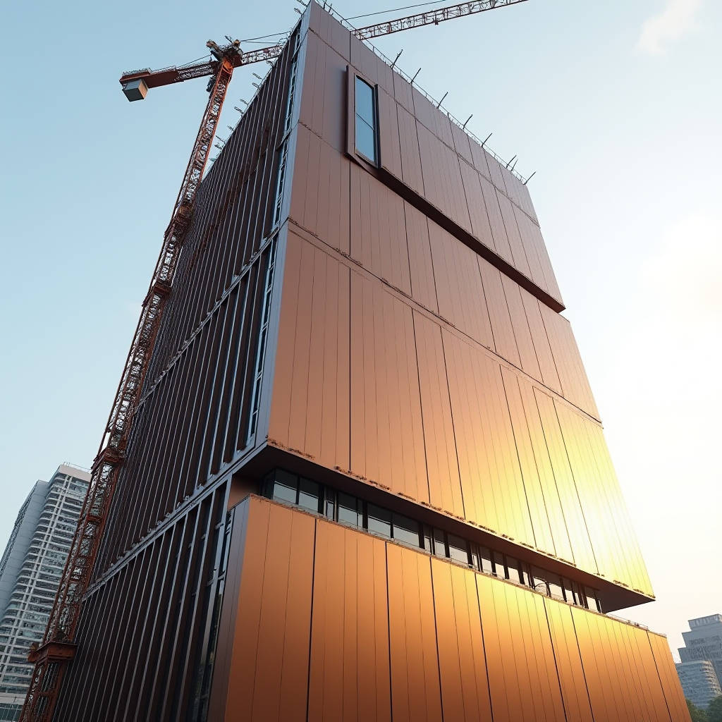
When a tower climbs past 30 storeys, the conversation among specifiers shifts. Wind pressure stops being a footnote and becomes the dominant structural variable. For solid aluminium high rise facade panels, getting the engineering right at 100 metres versus 300 metres is not a linear exercise. The difference between a 2.5 mm and 3.0 mm panel specification on a coastal high-rise can mean the difference between a 50-year facade and a warranty claim nobody wants to field. This article unpacks what actually matters when you are calculating wind loads, selecting reinforcement layouts, and specifying fixing systems for solid aluminium panels on tall buildings. No theory for its own sake. Just the parameters that show up in submittal reviews and shop drawing markups.
Why Wind Load Dictates Everything on a High-Rise Facade
On a low-rise commercial building, the structural engineer might glance at the cladding dead load and move on. On a tower, the script flips. Wind-induced suction forces at building corners can exceed 3.0 kPa, and the panel system must resist both positive pressure and negative suction without deforming, rattling, or transferring excessive load into the curtain wall mullions.
The governing standard in most international projects is ASCE 7 (Minimum Design Loads for Buildings and Other Structures), which provides the methodology for calculating design wind pressures based on building height, exposure category, and topographic factors. For projects in the Gulf region, Eurocode 1 (EN 1991-1-4) often applies, and the wind maps differ substantially from those used in Southeast Asia.
A solid aluminium panel at 3.0 mm thickness, when properly reinforced with aluminium stiffeners on the rear face, can typically span 600 mm to 900 mm between fixing points depending on the design wind load. Push that span to 1,200 mm without recalculating, and the panel will oil-can under negative pressure. The math is unforgiving.
Field Note: On a 42-storey tower in Manila, we reviewed shop drawings where the consultant had applied a uniform wind load across the entire elevation. The corner zones — within 1.5 m of building edges — were seeing 40% higher suction than the field area. The original 2.5 mm panel spec had to be upgraded to 3.0 mm with tighter stiffener spacing only in those corner zones. The contractor saved material by zoning the specification rather than upgrading the entire building envelope.
Panel Thickness, Alloy Selection, and the Stiffener Arithmetic
Solid aluminium high rise facade panels are typically specified in thicknesses of 2.0 mm, 2.5 mm, or 3.0 mm. The choice is not arbitrary. It flows from three inputs: design wind pressure, panel aspect ratio, and the fixing pattern.
Alloy 3003-H14 and 5052-H32 dominate the market. The 5052 alloy offers roughly 15% higher tensile strength and superior corrosion resistance in marine environments, which matters for towers within 5 km of a coastline. For inland projects, 3003-H14 is often sufficient and slightly more cost-effective. Both take PVDF coil coating without issue, and both can be brake-pressed or routed to the required geometry.
The stiffener system is where the real engineering happens. Aluminium extrusions — typically 6063-T5 profiles — are attached to the rear face of the panel using structural adhesive and, in many cases, mechanical fasteners. The stiffener spacing is calculated based on the panel's bending moment capacity. A common arrangement for a 1,200 mm × 3,000 mm panel on a 50-storey tower might use three horizontal stiffeners at 400 mm centers, with the end stiffeners set back 150 mm from the panel edges to allow for thermal movement.
Below is a practical reference table for solid aluminium panel specification based on building height and wind exposure:
| Building Height | Exposure Category | Recommended Panel Thickness | Typical Stiffener Spacing | Max Deflection (L/60) |
|---|---|---|---|---|
| Up to 30 m | Suburban (B) | 2.0 mm | 600 mm | 10.0 mm |
| 30 – 75 m | Urban (B) | 2.5 mm | 500 mm | 8.3 mm |
| 75 – 150 m | Open Terrain (C) | 3.0 mm | 400 mm | 6.7 mm |
| 150 – 300 m | Coastal (D) | 3.0 mm | 300 – 350 mm | 5.0 mm |
| 300 m+ | Coastal (D) | 3.0 mm + custom engineering | Project-specific FEA | Project-specific |
The deflection limit of L/60 (where L is the span between fixings) is a common benchmark in curtain wall specifications. Some consultants push for L/90 on prestige projects, which directly tightens stiffener spacing and increases the aluminium weight per square meter. These are the conversations that need to happen before the tender is priced, not after the material is in production.
Fixing Systems: The Difference Between a Quiet Facade and a Noisy One
Solid aluminium high rise facade panels are typically installed using one of two fixing philosophies: exposed fastener systems or concealed clip systems. The choice affects aesthetics, thermal performance, and long-term maintenance.
Exposed fastener systems use stainless steel screws with EPDM washers driven through the panel face into the supporting subframe. They are cheaper to fabricate and faster to install. The trade-off is visible fasteners and, over decades, the potential for washer degradation if UV-stabilized EPDM is not specified. For towers above 100 metres, exposed fasteners also create a slight discontinuity in the air barrier at each penetration point.
Concealed clip systems, sometimes called cassette systems, use aluminium extrusions or folded returns on the panel edges that engage with carrier rails fixed to the curtain wall mullions. The panel face is clean. Thermal movement is accommodated within the clip engagement, and the system can be engineered to allow individual panel removal for inspection or replacement — a non-negotiable requirement on many high-rise specifications.
The cost difference is not trivial. A concealed clip system might add 15–25% to the installed panel cost compared to exposed fasteners, but the lifecycle argument often wins on towers where access for re-sealing fasteners means swinging stages or rope access teams at 200 metres.
Pro Tip: When specifying concealed clip systems for high rise facade panels, always confirm the clip material. Some fabricators use 5052 aluminium for the panel face but switch to 6063-T6 for the clips. The galvanic compatibility is fine, but the thermal expansion coefficients differ slightly. Over a 4-metre panel length and a 60°C temperature swing, the differential movement can be 2–3 mm. The clip engagement depth must accommodate this, or the panels will bind at the corners during summer heat.
PVDF Coating: What the Spec Actually Means
The coating specification for high rise facade panels is almost always a PVDF (polyvinylidene fluoride) system, and the shorthand "70% PVDF" gets thrown around in tender documents with varying degrees of accuracy. The actual standard is AAMA 2605, which mandates a minimum of 70% PVDF resin in the colour coat, a total dry film thickness of at least 30 microns for a two-coat system, and specific performance criteria for colour retention, chalk resistance, and gloss retention after 10 years of South Florida exposure.
A three-coat system — primer, colour coat, and clear topcoat — pushes the total dry film thickness to 40–45 microns and provides additional UV protection for metallic and bright colours. On a 60-storey tower in direct sun, the difference between a two-coat and three-coat specification can be visible within 8–10 years, particularly on south-facing and west-facing elevations.
Colour consistency across production batches is measured using Delta E (CIE LAB). A Delta E of less than 1.0 is achievable with modern coil coating lines and is the standard expectation for high rise facade panels. When panels from different production runs are installed adjacent to each other on a tower, a Delta E of 2.0 or higher becomes noticeable to the naked eye under overcast sky conditions. This is why batch control and on-site panel sequencing matter as much as the coating specification itself.
Thermal Movement: The Gap That Engineers Forget
Aluminium expands at approximately 0.024 mm per metre per degree Celsius. On a 3.5-metre panel subjected to a 70°C temperature range (from -10°C winter night to 60°C summer sun on a dark-coloured panel), the linear expansion is roughly 5.9 mm. If the panel joints are specified at 10 mm, that leaves approximately 4 mm of residual gap after expansion — adequate for most conditions. But if the installer butts panels tight during winter installation, the summer expansion has nowhere to go, and panels buckle.
The joint width calculation for high rise facade panels must also account for building sway. Tall buildings move. A 250-metre tower might have a lateral drift of H/500 under wind load, which translates to 500 mm of movement at the top. The facade system must accommodate this inter-storey drift without panels disengaging from their fixings or sealant joints tearing.
This is where the interface between the solid aluminium panel system and the curtain wall unitised system becomes critical. The panel subframe must be designed to allow differential movement between the aluminium skin and the building structure. Slotted connections, typically with 10–15 mm of adjustment in both the horizontal and vertical directions, are standard practice. The slots must be oriented to permit movement in the direction of the anticipated drift, not perpendicular to it.
Logistics, Handling, and the Site Reality
A 3.0 mm solid aluminium panel measuring 1.5 m × 4.0 m weighs approximately 48 kg. That is manageable for two installers on a scissor lift at ground level. At 150 metres, with the panel swinging in the wind as the tower crane lifts it, the handling dynamic changes entirely.
Shipping protection for high rise facade panels is a subject that deserves its own specification section. Panels must be individually interleaved with polyethylene foam or protective film, crated in steel-framed timber boxes, and shipped with the crates oriented vertically to prevent flexing during transit. A single scratch on a PVDF-coated panel face at the jobsite means either a touch-up repair that will never match perfectly or a replacement panel that might take 6–8 weeks to fabricate and ship.
For international projects, the packaging specification should reference ISO 2248 (vertical impact drop test) and specify that crates be suitable for containerized sea freight with a minimum of two transshipment points. The cost of proper packaging is typically 3–5% of the panel material cost and is the cheapest insurance against site delays and variation claims.
Futeng® has supplied solid aluminium panels for multiple high-rise projects across Southeast Asia and the Middle East, and the feedback from site teams is consistent: the panels that arrive undamaged are the ones where the packaging was treated as an engineering deliverable, not an afterthought.
Fire Performance: Why Solid Aluminium Needs No Debate
Solid aluminium high rise facade panels are classified as non-combustible under most international building codes. Aluminium alloy itself carries a Euroclass A1 or A2 rating depending on the specific alloy and coating system, as tested to EN 13501-1. There is no plastic core, no polyethylene filler, and no combustible component to contribute to flame spread or molten droplet formation.
This is not a minor detail. In the wake of high-profile facade fires over the past decade, jurisdictions from the UK to the UAE to Australia have tightened their cladding regulations. The UK's Building Safety Act and the associated Approved Document B now effectively prohibit the use of combustible materials in the external walls of residential buildings over 18 metres. Solid aluminium panels with non-combustible insulation behind them meet these requirements without the need for extensive fire engineering justifications or desktop studies.
For specifiers, the fire compliance path is straightforward: specify the panel material, the insulation, and the complete wall assembly as a tested system. A solid aluminium panel with mineral wool insulation and a ventilated cavity is a well-understood, code-compliant rainscreen assembly that does not require project-specific fire testing in most cases.
Cost Drivers That Shape the Specification
The installed cost of solid aluminium high rise facade panels varies significantly by region, but the cost drivers are universal. Panel thickness, alloy grade, coating specification, stiffener complexity, fixing system type, and project location all feed into the final number.
A 2.5 mm PVDF-coated panel with a simple exposed fastener system might land at USD 180–220 per square metre installed in Southeast Asia, while a 3.0 mm panel with a three-coat metallic finish, concealed clip system, and complex geometry could push past USD 350 per square metre in a Gulf market with imported labour and logistics costs. These are indicative ranges, not quotes, but they frame the conversation.
The cost of the aluminium substrate itself is tied to LME (London Metal Exchange) pricing, and most reputable suppliers quote with an aluminium ingot price adjustment clause. If the LME aluminium price moves more than 5% between order and production, the panel price adjusts accordingly. This is standard practice and should be written into the supply contract, not treated as a surprise during fabrication.
What often gets overlooked in tender pricing is the cost of site adaptation. Tower facades are never perfectly square. The concrete frame will have tolerances of ±25 mm per floor, and the panel system must absorb those deviations through adjustable brackets and variable joint widths. The bracket system cost can be 10–15% of the total facade package, and underestimating it at tender stage is a reliable way to erode margin.
Making the Specification Work: From Drawing Board to Handover
The success of a solid aluminium high rise facade panel installation depends less on the panel itself — which is a well-understood product — and more on the interfaces. The panel-to-bracket connection, the bracket-to-slab edge connection, the sealant joint between panels, and the integration with windows, louvers, and balcony elements are where problems accumulate.
A practical sequence for the design team: start with the wind load study, move to panel thickness and stiffener layout, then define the fixing system, then the joint width and sealant specification, and finally the coating and colour. Each decision constrains the next. Changing the panel thickness after the fixing system has been engineered means redoing the structural calculations. Changing the colour from a standard PVDF to a metallic after the coating line has been scheduled means a 4-week delay and a price variation.
The specification should also address quality control during production. Third-party inspection of the coating line, including dry film thickness measurements, gloss readings, and colour verification against the approved sample, is standard for projects above a certain value. The inspection reports should be included in the operation and maintenance manual, not filed away and forgotten.
For the site team, the priority is sequencing. Panels should be delivered to the floor where they will be installed, not stockpiled at ground level and double-handled. Each panel should be inspected upon uncrating, and any damage documented before installation. A panel installed with a scratch is a defect. A panel scratched after installation is a variation claim. The distinction matters.
Solid aluminium high rise facade panels, when properly specified, fabricated, and installed, deliver a facade that performs predictably for decades. The engineering is established. The standards are mature. The supply chain, from coil coaters to fabricators to bracket manufacturers, is well-developed. The variable is the attention to detail at each interface — and that is where the project team's experience, or lack of it, shows up in the finished building.