Custom Metal Panel Fabrication Flatness Engineering for Large Format Solid Aluminium Cladding
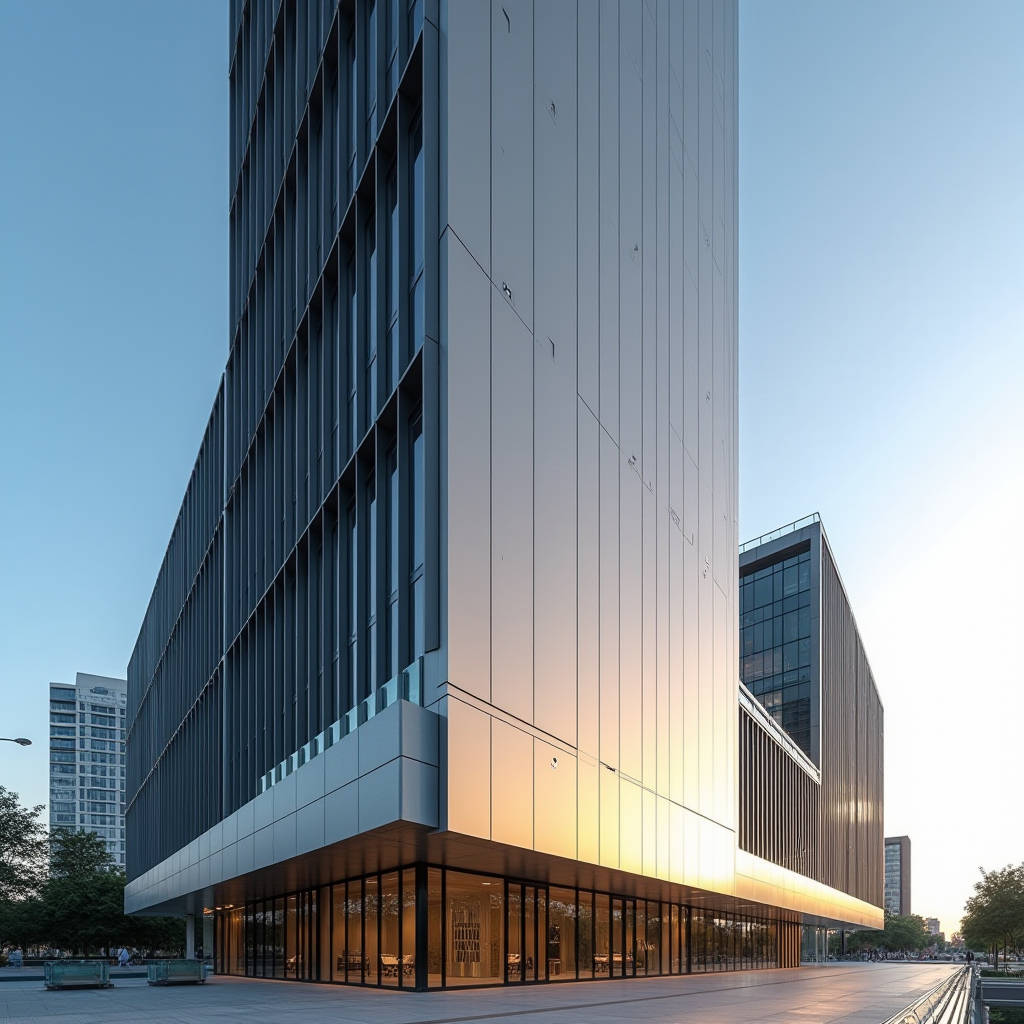
When a façade contractor sends an RFQ for 3,200 custom aluminium panels destined for a 42-storey mixed-use tower in Singapore, the spreadsheet doesn't ask about aesthetics first. It asks about flatness. Specifically, it asks whether the 2.5mm solid aluminium sheets — some stretching 1,800mm by 3,600mm — can hold a deviation under 0.5mm across the diagonal after routing, folding, and reinforcing. That single tolerance line separates factories who understand curtain wall physics from sheet metal shops who don't. Custom metal panel fabrication, when the project involves large-format solid aluminium cladding, isn't primarily a manufacturing problem. It's a thermal movement and structural restraint problem disguised as a panel supply contract.
This article unpacks the engineering logic behind large-format solid aluminium panel flatness: what causes post-installation warping, how stiffener design and attachment methods interact with wind load and thermal cycling, and what procurement managers should specify in technical submittals before the first sheet hits the laser bed. The focus stays on solid aluminium cladding panels — 2.0mm, 2.5mm, and 3.0mm gauges — with PVDF coating systems applied to AAMA 2605 standards. No composites. No sandwich panels. Just monolithic metal and the physics that governs it.
Why Large Panels Warp: The Three Forces Fabricators Can't Ignore
A 3.0mm solid aluminium panel measuring 2,000mm by 4,000mm weighs roughly 65 kg. Hung vertically on a curtain wall carrier system, it faces three distinct forces simultaneously: gravity acting on its own mass, positive and negative wind pressure cycling across the building face, and thermal expansion that can push the panel's long edge outward by 2.4mm during a 40°C temperature swing. Most warping complaints trace back to one of these forces being underestimated during the shop drawing phase.
Thermal expansion deserves particular attention. Aluminium's coefficient of linear thermal expansion sits at approximately 23.8 × 10⁻⁶ /°C. For a 4-metre panel experiencing a 50°C delta between fabrication shop temperature and installed conditions under direct sun, the linear growth reaches 4.76mm. If the panel perimeter is fixed rigidly — no allowance for movement at anchor points — that expansion converts directly into buckling stress. The panel bows outward. Once it yields, it doesn't spring back.
Field Note: On a 2022 project in Dubai, we tracked 68 large-format panels that developed visible oil-canning within six months of installation. Root cause analysis traced it to continuous stiffener beads welded edge-to-edge with zero slip joints. The stiffeners themselves became thermal bridges that transferred expansion stress into the panel face. The fix for subsequent phases: intermittent stiffener attachment with slotted holes at 300mm spacing, allowing 1.5mm of longitudinal float per stiffener.
Wind Load and the Stiffener Calculation That Gets Skipped
Most project specifications reference ASCE 7 for wind load determination. The architect's structural engineer calculates design pressure based on building height, exposure category, and local wind speed data. That number — say, 2.4 kPa for a 60-metre elevation in Exposure Category B — determines the maximum allowable deflection for the cladding panel under service load. The industry benchmark for solid aluminium panels, drawn from AAMA 508 and common curtain wall practice, limits deflection to L/60, where L is the span between attachment points.
Here's where the fabrication engineering gets real. A 1,500mm span with L/60 deflection limit allows 25mm of movement under design wind load. That's generous for structural safety but visually unacceptable on a smooth metal façade. Most experienced fabricators tighten this to L/90 or even L/120 for visible elevations. Achieving that requires a stiffener layout that distributes load paths without adding excessive weight — and without creating the thermal restraint problem described above.
The stiffener itself is typically a 3.0mm aluminium hat section or flat bar, mechanically attached or intermittently welded to the panel back. The attachment method matters enormously. Continuous welding along the stiffener length creates a heat-affected zone that locally anneals the panel material, reducing yield strength by up to 40% in the weld vicinity. The alternative — structural adhesive bonding combined with mechanical fasteners — preserves the panel's temper but requires surface preparation and curing time that some production schedules resist.
Material Selection: Why Temper Designation Changes Everything
Not all 2.5mm aluminium sheet behaves the same way under brake press forming. The temper designation — the H14, H22, or H32 suffix on alloy 3003 or 5052 — dictates how the material responds to bending, how much springback to expect, and whether the formed panel holds its geometry after stress relief. For custom metal panel fabrication involving large flat faces, the conversation starts with alloy selection and gets specific about temper.
Alloy 3003-H14 remains the workhorse for architectural cladding. It offers moderate strength (145 MPa tensile), excellent corrosion resistance, and predictable formability. But on panels exceeding 1,200mm in width, H14 temper can exhibit noticeable springback after brake forming — the flange angle opens slightly after the press releases. Compensating for this requires over-bending by 2° to 3°, a value that must be dialed in per batch because temper consistency varies between aluminium mills.
Alloy 5052-H32 steps in when the panel needs higher strength (215 MPa tensile) or when the project site sits in a coastal environment where salt spray resistance matters. The trade-off: 5052 work-hardens faster during forming, which means tighter bend radii risk micro-cracking. The minimum inside bend radius for 5052-H32 is typically 1.5 times the material thickness, versus 1.0 times for 3003-H14. Get this wrong on the shop drawing and the panel cracks at the fold line — sometimes visible immediately, sometimes after the first thermal cycle.
| Property | 3003-H14 | 5052-H32 | Engineering Significance |
|---|---|---|---|
| Tensile Strength | 145 MPa | 215 MPa | Higher strength allows thinner gauge for same load |
| Yield Strength | 125 MPa | 160 MPa | Determines onset of permanent deformation |
| Min. Bend Radius | 1.0t (2.5mm for 2.5mm sheet) | 1.5t (3.75mm for 2.5mm sheet) | Affects corner detail design and tooling setup |
| Springback Angle | 2°–3° | 3°–5° | Requires over-bend compensation in press programming |
| Corrosion Resistance | Good (industrial) | Excellent (marine) | Decisive for coastal or high-humidity projects |
| Thermal Conductivity | 160 W/m·K | 138 W/m·K | Affects thermal bridging through stiffener system |
The Attachment System: Where Flatness Lives or Dies
Panel flatness doesn't end at the factory door. The attachment method — how the fabricated panel connects to the curtain wall mullion or sub-frame — exerts as much influence on final appearance as the stiffener layout. Three common systems dominate solid aluminium cladding installation, and each imposes different constraints on the panel fabrication tolerances.
Exposed Fastener (Face-Screwed) Systems
The simplest and most economical approach. The panel face is drilled and screwed directly to the support structure, with fastener heads visible on the finished surface. For custom metal panel fabrication, this method demands precise hole placement — typically ±0.5mm — because the fastener head sits flush in a countersunk or pan-head configuration. Any misalignment telegraphs visibly across the façade. The upside: the panel is mechanically restrained at multiple points, which helps control flatness. The downside: thermal movement concentrates at the panel edges, and the fastener holes eliminate any possibility of the panel floating freely.
Concealed Clip (Rainscreen) Systems
The dominant method for high-end commercial façades. Panels hang on extruded aluminium clips or carrier rails, with no fasteners visible from the exterior. The panel fabrication must now account for a different set of precision requirements. The folded return leg — the panel edge that hooks onto the clip — must be parallel to the panel face within 0.3mm across its length. If the return leg varies by even 0.5mm, the panel sits proud at one corner and recessed at another. The resulting shadow line reads as waviness, even if the panel face itself is perfectly flat.
Pro Tip: When specifying concealed-clip panels, require the fabricator to submit a dimensional inspection report measuring return-leg height at six points per panel edge (quarter-points plus ends). Acceptable tolerance: ±0.3mm. Reject the batch if any single measurement exceeds ±0.5mm. This one check catches more flatness problems than any visual inspection of the panel face.
Unitized Panel Systems
For high-rise construction where speed of installation governs the schedule, panelized or unitized systems integrate the solid aluminium panel, insulation, and sub-frame into a single pre-assembled unit hoisted into place. The fabrication challenge shifts from individual panel flatness to system-level geometric control. The panel, now bonded or mechanically fastened to a steel or aluminium sub-frame, must maintain flatness across the entire unit — typically 1,500mm by 3,600mm or larger — while the unit is lifted, rotated, and bolted to the floor slab. Differential thermal expansion between the aluminium skin and the steel sub-frame introduces shear stress at the connection points that must be accounted for in the fastening detail.
Shop Drawing Review: The Five Checks That Prevent Site Disputes
Most flatness-related claims originate not in the factory but in the shop drawing approval process. The specification says "panels shall be free from oil-canning and visible distortion." That's subjective. The shop drawing must translate subjective language into measurable criteria. Here are the five checks that separate a thorough technical submittal from a superficial one.
1. Stiffener Layout Drawings with Deflection Calculations. The fabricator should submit a stiffener plan view for each unique panel type, annotated with the calculated maximum deflection under the project-specified wind load. The calculation should reference the specific alloy and temper, not a generic "aluminium" value. If the submittal lacks these calculations, the reviewer cannot verify whether the stiffener spacing is adequate.
2. Thermal Movement Accommodation Detail. Look for a specific drawing or note showing how each panel attachment point allows movement. Slotted holes, sliding clips, or flexible connections should be called out with the expected movement range. A submittal that shows all connections as fixed is a red flag for panels longer than 1,200mm.
3. Weld Map for Assembled Panels. If the panel incorporates welded stiffeners or corner joints, the submittal should include a weld map showing weld type (TIG or MIG), length, spacing, and whether the weld is continuous or intermittent. Intermittent welds should specify the weld segment length and the gap between segments.
4. Flatness Tolerance Specification. The submittal must state the flatness tolerance numerically. A common reference is ASTM E330/E330M for structural performance, but flatness itself is often specified as a deviation from a straight edge placed across the panel diagonal. Industry practice for architectural solid aluminium panels: maximum deviation of 0.5mm per 300mm of diagonal length, with an overall maximum of 2.0mm regardless of panel size.
5. Coating Thickness and Cure Verification. PVDF coatings applied to AAMA 2605 standards require a minimum total dry film thickness of 30 microns (three-coat system) or 25 microns (two-coat system). The submittal should include the coating specification, the applicator's qualification, and the proposed test method for verifying cure. Under-cured PVDF can delaminate under thermal cycling, which initially appears as a flatness problem when the coating separates from the substrate.
When Factory Flatness Meets Site Reality
A panel that measures flat on the factory inspection table can still look wavy on the building. The difference between the two conditions often comes down to the support structure. If the curtain wall mullions or sub-frame rails are installed with a deviation exceeding 3mm over a 3-metre span, the panel inherits that deviation regardless of its own flatness. The panel is flexible enough to follow the substrate — that's a feature, not a defect, but it means the installation crew must verify substrate flatness before hanging panels.
This is where the procurement logic shifts. A project team that sources panels from the lowest bidder without auditing the fabricator's quality control process often discovers problems too late. The panels themselves may be within tolerance, but if the fabricator hasn't provided clear installation tolerances for the supporting structure, the site team has no benchmark to enforce. The result: panels that meet the factory spec but fail the visual inspection, and a dispute over who bears responsibility.
Fabricators with deep experience in custom metal panel fabrication — including companies like Futeng® that handle both the engineering and the production under one roof — typically include substrate tolerance requirements in their installation documentation. They specify that the supporting surface must be planar within ±2mm over any 2.4-metre length, measured with a taut string line or laser level. This single requirement, enforced before panel installation begins, prevents the majority of post-installation flatness complaints.
Quality Control Protocol: Measuring What Matters
Visual inspection under shop lighting catches gross defects but misses the subtle distortions that become visible under the low-angle sunlight typical of building façades. A proper QC protocol for large-format panels combines quantitative measurement with controlled visual assessment.
The quantitative check uses a calibrated straight edge — typically a precision-ground aluminium beam — placed across the panel diagonal. A feeler gauge measures the gap between the straight edge and the panel surface at the point of maximum deviation. For panels under 2 square metres, the maximum allowable gap is 1.0mm. For panels between 2 and 6 square metres, the limit increases to 2.0mm. Panels exceeding 6 square metres require individual engineering assessment because the straight-edge method becomes less reliable at very large dimensions.
The visual check requires a controlled setup: the panel should be positioned vertically, illuminated by a diffuse light source at a 15° grazing angle, and viewed from a distance of 3 metres. Under these conditions, surface undulations that measure within tolerance can still produce visible shadow patterns. The acceptance criterion should specify that no visible oil-canning is permitted under these viewing conditions — a standard referenced in AAMA 508 and similar industry guidelines.
For projects requiring third-party verification, the fabricator should be prepared to submit panels to an independent testing laboratory for ASTM E330 structural performance testing. This test applies the design wind load to a mock-up section of the façade and measures deflection under both positive and negative pressure. The test report provides objective evidence that the panel system — including stiffeners, attachments, and the supporting structure — performs as designed.
Packaging and Logistics: Preserving Flatness Through the Supply Chain
A panel that leaves the factory flat can arrive on site with a permanent set if the packaging doesn't support the panel adequately. For large-format solid aluminium panels, the standard packaging method involves stacking panels horizontally on purpose-built steel stillages, with closed-cell foam separators between each panel. The stillage base must be rigid enough to prevent flexing when lifted by forklift — a stillage that sags under its own load transfers that sag into the bottom panels.
For ocean freight shipments, additional considerations apply. Condensation inside shipping containers can cause water staining on bare aluminium edges if the panels aren't adequately protected. VCI (volatile corrosion inhibitor) paper or desiccant packs should be included. The stillage should be secured to the container floor to prevent shifting during transit, and the container should be specified as "below deck" stowage to minimize temperature extremes.
These logistics details matter because a panel that arrives warped creates a cascade of problems: the installation schedule slips while replacement panels are fabricated, the contractor files a claim, and the project team loses confidence in the supply chain. The cost of proper packaging — typically 3% to 5% of the panel value — is a fraction of the cost of replacing even one container of damaged panels.
For project teams evaluating suppliers, the packaging specification should be part of the technical submittal review. Ask for photographs of the proposed stillage design, the foam separator specification, and the container loading plan. A fabricator that can't produce these documents hasn't shipped enough large-format panels to understand the risk.
Making the Specification Work: Practical Takeaways
Large-format solid aluminium panel flatness isn't a single parameter — it's a system behaviour that emerges from the interaction of material properties, fabrication methods, attachment design, substrate quality, and handling procedures. The specification that controls flatness effectively doesn't just state a tolerance; it addresses each link in the chain.
For the procurement manager writing the next RFQ, the actionable items are clear: require stiffener deflection calculations in the shop drawing submittal, specify thermal movement accommodation details, demand a numerical flatness tolerance referenced to a measurable standard, and include packaging and substrate tolerance requirements in the scope of work. These four requirements, enforced consistently, eliminate the ambiguity that leads to disputes.
The factories that perform well on large-format custom metal panel fabrication are the ones that treat flatness as an engineering discipline rather than a quality control checkbox. They calculate before they cut. They measure what they've calculated. And they document what they've measured. When the 3,200 panels go up on that Singapore tower and the façade reads as a single continuous plane from street level to penthouse, the credit belongs to the engineering that happened months before the first sheet of aluminium arrived at the factory.