Architectural Panel Fabrication Protocol Standards That Prevent Batch Drift Across Multi Line Projects
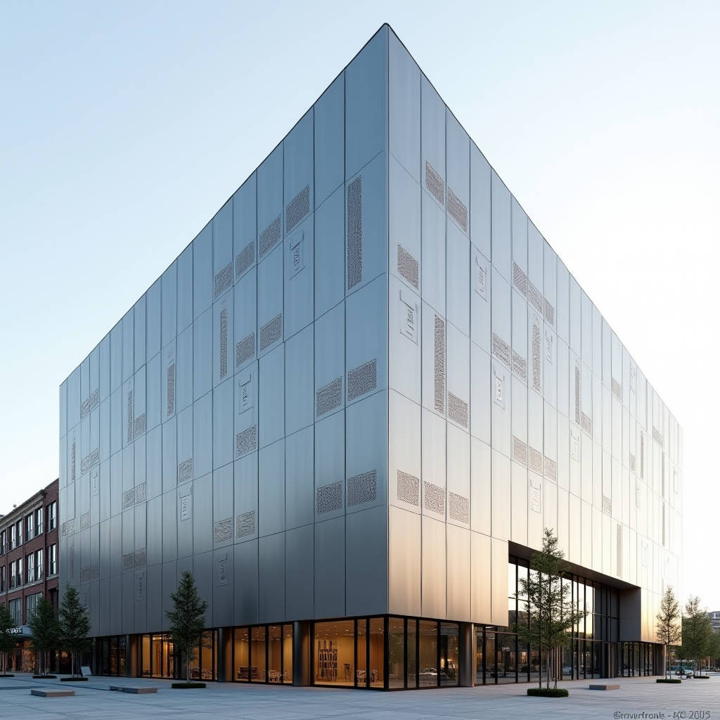
On a 42-storey tower in Kuala Lumpur, the general contractor faced a recurring headache: aluminium panels arriving from three different fabrication facilities showed visible colour drift when installed side by side. The root cause wasn't the coating chemistry. It was the absence of a unified fabrication protocol that governed how each panel moved from coil to crate. Architectural panel fabrication, when executed across multiple production lines for a single project, demands a level of process standardisation that most specifications overlook entirely. This article dissects the fabrication variables that directly impact batch-to-batch consistency on large-scale façade programmes—and what procurement teams should lock down before the first sheet enters the CNC line.
The Hidden Variables That Break Batch Consistency
Most project specifications for architectural panel fabrication are surprisingly thin. They reference ASTM B209 for aluminium sheet, AAMA 2605 for PVDF coating, and maybe a flatness tolerance. What they rarely address is how the same 2.5mm solid aluminium panel can emerge from two different production bays with measurable differences in edge straightness, hemming radius, and even perceived colour.
The issue compounds on projects exceeding 5,000 m² of cladding. At that scale, a single fabrication line cannot meet delivery schedules. The work splits across multiple lines or even multiple facilities. Without a locked fabrication protocol, each line operator makes micro-decisions: tooling wear limits, routing speeds, bending sequences. These accumulate into visible discrepancies.
Three fabrication variables deserve particular scrutiny during technical submittal review:
- CNC routing speed and tool change intervals. A dull router bit generates burrs and micro-chatter along panel edges. On a single panel, this is cosmetic. Across 800 panels, the edge quality difference between Line A (fresh tooling) and Line B (tooling near end-of-life) becomes a site complaint.
- Bending brake calibration frequency. Hydraulic press brakes drift over a production shift. If one line calibrates every 4 hours and another every 8 hours, flange angles will differ by 0.5°–1.0°. That difference translates to uneven shadow gaps on installed panels.
- Hemming and edge return consistency. Panel edges folded for open-joint systems require a precise 20mm return. A ±1mm tolerance on paper becomes a visible waviness across a 60-metre elevation when fabrication lines interpret the allowance differently.
Field Note: On a recent Middle Eastern project, we traced a 2.3mm discrepancy in panel-to-panel joint width back to two CNC machines using different firmware versions. The G-code was identical. The toolpath interpolation was not. Always request the machine make, model, and control system version in the fabrication quality plan.
Coil Traceability: The Foundation of Colour Consistency
PVDF coating batch management starts long before the spray line. Aluminium coil from the mill carries a heat number and a production date. Even within the same alloy designation (AA 3003 or AA 5005, depending on the specification), minor variations in chemistry and rolling parameters affect how the coil accepts pre-treatment and how the PVDF topcoat flows.
For architectural panel fabrication, the rule is straightforward: one elevation, one coil batch. When that is impossible due to project scale, the fabrication protocol must include a coil-mapping document that assigns specific coil batches to specific building zones. The transition between batches happens at architectural breaks—floor transitions, expansion joints, or building corners—never mid-elevation.
The pre-treatment stage is equally critical. Chromate conversion coating (or chrome-free alternatives for projects under EU REACH compliance) must maintain consistent dwell time, bath temperature, and rinse conductivity. A 15-second variance in dwell time alters the coating's adhesion profile. Six months into service, that variance shows up as micro-blistering on panels that passed initial inspection.
Futeng® has addressed this in their multi-line fabrication setup by implementing a centralised coil management system that tracks each coil from mill certificate through to finished panel crate. For projects where batch splitting is unavoidable, their protocol includes a spectrophotometer reading at the start and end of each production run, with Delta E values logged against the project master standard.
PVDF Application: Why AAMA 2605 Is a Starting Point, Not a Finish Line
AAMA 2605 is the industry benchmark for high-performance architectural coatings. It mandates a minimum total film thickness of 30 microns for a three-coat system, with specific requirements for gloss retention, colour retention, and chalk resistance after 10 years of South Florida exposure. But the standard leaves room for interpretation in how those microns are built up.
Three-coat PVDF systems typically consist of a primer (5–8 microns), a colour coat (18–22 microns), and a clear topcoat (8–12 microns). The ratio matters. A heavy primer and thin colour coat saves cost but reduces hiding power and UV resistance. A thin clear coat exposes the colour layer to accelerated erosion in coastal or high-UV environments.
For architectural panel fabrication, the spray line configuration directly affects film uniformity. Vertical electrostatic spray lines produce different film distribution patterns than horizontal reciprocating lines. Panels with deep returns or complex perforation patterns present shadow zones where film thickness drops below specification. The fabrication protocol must specify how these zones are measured and what constitutes an acceptable minimum.
| Coating Parameter | AAMA 2605 Minimum | Recommended for Coastal / High-UV | Inspection Method |
|---|---|---|---|
| Total Film Thickness (3-coat) | 30 μm | 38–42 μm | ASTM D7091 (eddy current) |
| Primer Layer | Not individually specified | 6–8 μm | Cross-section microscopy |
| Colour Coat (Kynar 500® / Hylar 5000®) | Not individually specified | 22–25 μm | Cross-section microscopy |
| Clear Topcoat | Not individually specified | 10–12 μm | Cross-section microscopy |
| Gloss Retention (10-year) | ≥ 50% | ≥ 70% | ASTM D523 / D4214 |
| Colour Retention (Delta E, 10-year) | ≤ 5.0 | ≤ 3.0 | ASTM D2244 |
| Chalk Resistance (10-year) | Rating ≥ 8 | Rating ≥ 9 | ASTM D4214 |
| Pencil Hardness (post-cure) | ≥ HB | ≥ F | ASTM D3363 |
The Kynar 500® or Hylar 5000® resin content is the single most consequential specification in PVDF coating. AAMA 2605 requires a minimum of 70% PVDF resin in the colour coat (by weight of total resin solids). Below that threshold, the coating's weatherability drops sharply. Some fabricators offer "PVDF-based" systems at 50–60% resin content to reduce cost. These will not perform to the 10-year South Florida benchmark. Insist on the full 70% minimum and request the coating supplier's formulation certificate.
Fabrication Tolerances: What the Drawing Says vs. What the Site Receives
Architectural panel fabrication tolerances are typically specified as ±1.0mm on length and width, ±0.5mm on hole positions, and ±1.5mm on diagonal difference. These numbers work for individual panels laid on an inspection table. They become less meaningful when 200 panels are installed across a continuous elevation.
The real metric is cumulative tolerance stacking. If each panel is within ±1.0mm of nominal width, a row of 30 panels could theoretically accumulate a 30mm deviation. In practice, the distribution is random, and the cumulative error is closer to ±3–5mm over 30 panels. But that still requires the installation team to absorb the variance in the joint system.
Three tolerance-control strategies should be embedded in the fabrication protocol:
- Statistical process control (SPC) on critical dimensions. Rather than 100% inspection of every panel, sample 5 panels per production batch and plot the key dimensions on a control chart. If the process mean drifts beyond 0.5mm from nominal, halt production and recalibrate.
- Pre-sorting panels by installation zone. Panels measured at the upper end of the tolerance band should be grouped and assigned to the same elevation zone. This converts random variance into a consistent offset that the installer can compensate for with a single adjustment.
- Mock-up validation at full scale. A 3-panel sample is not a mock-up. A proper fabrication mock-up should include at least 12–15 panels covering a corner condition, a window opening, and a typical field area. This reveals how fabrication tolerances interact with the substructure and joint system.
Pro Tip: When reviewing fabrication shop drawings, check whether the panel dimensions are shown as "finished size" or "blank size." A 1,200mm finished panel with a 20mm return on each side requires a blank of 1,240mm. If the fabricator dimensions from the blank and the tolerance is applied to the blank, the finished panel will be 1–2mm oversize. This single detail has caused more site rework than any other fabrication issue.
The Substructure Interface: Why Fabrication Precision Must Match Installation Reality
A panel fabricated to ±0.5mm precision will still look wrong if the supporting substructure is installed to ±5mm. The fabrication protocol cannot exist in isolation. It must account for the interface between the panel's fixing system and the site-installed framework.
For rainscreen systems using aluminium T-profiles or hat channels, the critical interface dimension is the distance from the panel's rear face to the centreline of the fixing slot. If the substructure is 3mm out of plane, the panel must accommodate that deviation through slotted holes or adjustable brackets. The slot length, slot width, and the diameter of the fixing screw or rivet must be specified in the fabrication drawing with the substructure tolerance in mind.
For unitised curtain wall systems, the panel is typically fixed to a pre-assembled frame in the factory. This shifts the tolerance interface from site to factory. The frame jig accuracy becomes the controlling factor. A jig that is out of square by 0.5mm over 3 metres will produce every panel with the same error. The fabrication protocol should include a jig calibration schedule and a first-article inspection report for each jig setup.
The Centre for Window and Cladding Technology (CWCT) provides detailed guidance on tolerance interfaces between façade components. Their technical notes on rainscreen framing tolerances are a useful reference for specifying the fabrication-to-installation tolerance chain.
Packaging, Logistics, and the Final Quality Gate
Architectural panel fabrication does not end at the factory exit. A panel that leaves the facility in specification can arrive on site with scratches, edge damage, or flatness distortion if the packaging and logistics protocol is inadequate.
Solid aluminium panels—particularly large-format panels exceeding 2.4 metres in any dimension—are susceptible to flexural damage during transport. The standard practice of stacking panels with interleaving foam sheets works for small panels. For large panels, the stack weight alone can cause the bottom panel to deform if the support surface is not perfectly flat.
A robust packaging protocol for international shipments should include:
- Custom timber crates with internal bracing. Panels should be stored vertically or at a slight angle, not flat-stacked. Each panel should be separated by a minimum 10mm air gap using foam or timber spacers.
- Edge protection on all returns. The 20mm or 25mm return edge is the most vulnerable point during handling. Protective U-channel PVC or rubber edge guards should be applied before crating.
- Moisture barrier for sea freight. PVDF-coated panels are corrosion-resistant, but the cut edges of aluminium are not. A VCI (volatile corrosion inhibitor) film or desiccant pack inside the crate prevents edge oxidation during 4–6 weeks at sea.
- Panel-by-panel inspection record. Each crate should include a QR code linking to the inspection data for every panel inside. This allows the site team to verify that any damage occurred in transit rather than in fabrication.
For projects under FOB or CIF terms, the packaging specification should be a line item in the fabrication contract, not an afterthought. The ISO 2244:2000 standard for horizontal impact testing provides a benchmark for crate durability, though most architectural panel shipments require more stringent protection than the standard minimum.
Digital Fabrication Data: Closing the Loop Between Design and Production
The architectural panel fabrication workflow increasingly relies on digital data transfer from the architect's BIM model to the fabricator's CAM system. When this data pipeline works, it eliminates manual dimension take-off errors and accelerates shop drawing approval. When it breaks, the consequences cascade through the entire programme.
The critical handover point is the IFC or STEP file export from the design model. Not all BIM software exports panel geometry with the same fidelity. Curved surfaces, in particular, may be tessellated into facets rather than exported as true curved geometry. The fabricator's CAM system then interprets a faceted approximation, producing panels that do not match the architect's intent.
A fabrication protocol that includes digital data transfer should specify:
- The file format and version for geometry exchange (IFC 2x3 or 4, STEP AP242, or native CAD format).
- The acceptable deviation between the design model surface and the CAM toolpath surface (typically ≤ 0.2mm for flat panels, ≤ 0.5mm for curved panels).
- The attribution data carried with each panel: panel ID, zone, material grade, coating code, and fixing type.
The buildingSMART International standards for IFC provide a framework for this data exchange, though project-specific implementation details must be agreed between the design team and the fabricator during the shop drawing phase.
Specifying the Fabrication Protocol: A Checklist for Procurement
For procurement managers and façade consultants, the key takeaway is that architectural panel fabrication quality cannot be secured by a material specification alone. The process specification is equally important. The following elements should form part of any fabrication quality plan submitted for approval:
- Coil traceability matrix linking mill certificates to building zones
- PVDF resin content certification (minimum 70% Kynar 500® or Hylar 5000®)
- Spray line configuration and film thickness measurement methodology
- CNC machine model, control system version, and tool change interval
- Press brake calibration frequency and method
- Statistical process control plan for critical dimensions
- Jig calibration schedule (for unitised panel fabrication)
- Packaging specification including crate design and corrosion protection
- Digital data exchange protocol between design model and CAM system
- First-article inspection and full-scale mock-up requirements
These are not exotic requirements. They represent the difference between a fabricator who treats each project as a custom exercise and one who applies a repeatable, auditable process. For projects exceeding 3,000 m² of solid aluminium cladding, the cost of not specifying these controls almost always exceeds the cost of implementing them.
The industry has the standards. ASTM B209 covers the base metal. AAMA 2605 covers the coating. What remains is the fabrication discipline that connects the two—and that is where project outcomes are won or lost.