Engineering an Aluminum Fins Facade for Wind Load, Thermal Movement and Coastal Corrosion
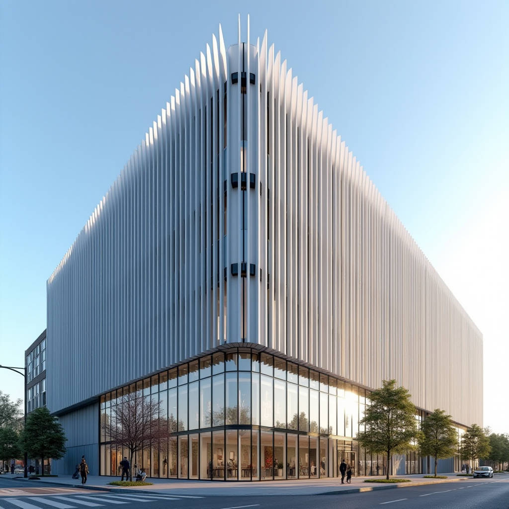
The aluminum fins facade has moved from a purely decorative trend into a load-bearing, performance-critical building envelope component. Contractors and procurement teams now face a recurring question: how do you specify a fin system that delivers the visual rhythm clients demand while surviving wind uplift, thermal cycling, and coastal corrosion for decades? The answer sits in the material grade, the coating system, and the structural fixings behind the profile. This article walks through the engineering data that separates a properly engineered aluminum fins facade from a failure waiting on the warranty sheet. We focus on solid aluminium cladding panels and extruded fin profiles, not composite boards, because solid material gives you predictable stiffness, weldable connections, and a fire performance record that composite cores cannot match.
Why Solid Aluminium Beats Composite for Fin Profiles
Fin profiles carry real loads. A vertical fin spanning three storeys acts as a cantilever under wind pressure, and its deflection governs the whole facade's performance. Solid aluminium, typically 6063-T5 or 6063-T6 extruded alloy, provides a consistent modulus of elasticity around 69 GPa. Composite panels, by contrast, have a core that contributes almost nothing to bending stiffness, so a fin built from composite material must be significantly deeper or thicker to reach the same deflection limit. That extra depth adds cost, weight, and wind load to the supporting structure. For procurement teams comparing quotes, the honest comparison is not price per square metre of skin but total installed cost per metre of fin span at a specified deflection.
Solid profiles also allow clean welded joints and mechanical connections that hold tolerances over time. When a facade relies on the fins for solar shading, the gap between fins controls the shading coefficient and the daylight factor. If the profile twists or the bracket loosens, the visual rhythm breaks and the energy model drifts from the as-built reality. Solid aluminium keeps the geometry stable through the building's life, which is why the majority of high-rise fin facades specify extruded solid profiles rather than folded composite sections.
Structural Engineering of Fin Facades
The structural design of an aluminum fins facade starts with the wind load calculation to the local code. For a building in a coastal zone, the design wind pressure can exceed 2.5 kPa at the parapet, and the fin must transfer that load through its bracket into the subframe. The critical checks are the fin's bending stress, its deflection at the serviceability limit state, and the pull-out capacity of the anchors. A common rule of thumb for a cantilevered fin is to limit tip deflection to span divided by 150, though many architects push for span over 200 to keep the shadow line crisp.
Thermal movement is the second load case that gets underestimated. A 3-metre aluminium fin exposed to a 60°C temperature swing expands roughly 3.9 mm. If the fixing system does not allow that movement, the fin will bow, the coating will craze at the fixing points, and the bracket will fatigue. The solution is a slotted or sliding bracket detail that lets the fin grow and shrink freely while still resisting out-of-plane wind load. This detail is where cheap systems fail and where a properly engineered system earns its cost.
For contractors, the practical implication is that the bracket specification is as important as the profile specification. A fin system with a 3 mm thick profile but a 1.5 mm bracket is structurally unbalanced. The bracket should be designed to the same load case as the fin, with a safety factor applied to the connection. The aluminium association's guidance on structural design of aluminium, covered under the relevant EN 1999 provisions, gives the load and resistance factors that should be applied to both the profile and its fixings.
Coating Systems and Corrosion Performance
Coating is the first line of defence against corrosion, and it determines the warranty period the manufacturer will offer. For exterior fins, the industry standard is a two-coat or three-coat PVDF (polyvinylidene fluoride) system applied to a pre-treated surface. The film thickness should be verified on site, not taken from the datasheet. A three-coat PVDF system typically delivers a dry film thickness of 25 to 30 microns, and this is the figure that should appear in the specification and be checked with a magnetic thickness gauge on delivered profiles.
The table below summarises the practical performance parameters that procurement teams should compare across coating options for an aluminum fins facade.
| Coating System | Typical DFT (microns) | Salt Spray Resistance (hours to failure) | UV / Colour Retention | Typical Warranty (years) |
|---|---|---|---|---|
| Two-coat PVDF | 20–25 | 3,000–4,000 | Good | 10–15 |
| Three-coat PVDF | 25–30 | 4,000–5,000 | Excellent | 15–20 |
| Anodised (Class 1) | 20–25 (oxide) | 2,500–3,500 | Very good | 10–15 |
| Polyester (interior only) | 20–25 | 500–1,000 | Poor | 5 |
For coastal projects, specify the three-coat PVDF system and require the supplier to provide a salt-spray test certificate to the relevant ISO standard. The difference between a two-coat and three-coat system is not just marketing; the third clear coat adds a protective layer that slows chalking and fading in high-UV environments.
Solar Shading and Thermal Performance
The functional reason most clients accept the cost of an aluminum fins facade is solar control. Horizontal fins above glazing block high-angle summer sun while admitting low-angle winter sun, which is the classic response to a south-facing elevation. Vertical fins suit east and west elevations where the sun is low in the sky. The shading coefficient of the facade depends on the fin depth, the fin spacing, and the angle of the profile relative to the glazing.
A practical starting point is a fin depth equal to 60 to 80 percent of the spacing between fins. At that ratio, the facade typically blocks 40 to 60 percent of incident solar radiation during peak hours, which translates into a meaningful reduction in the cooling load and the size of the HVAC plant. The energy model should be run with the actual fin geometry, not a generic shading factor, because the difference between a 45-degree and a 60-degree fin angle changes the annual solar gain by several percent.
Ventilation is the second functional benefit. Fins mounted on standoffs leave a ventilated cavity behind the profile, which allows air to move and prevents moisture build-up behind the facade. This cavity also helps manage condensation in humid climates. The ventilation gap should be at least 50 mm to be effective, and the cavity should be detailed with a drainage path at the base so that any water that enters can escape.
Installation and Site Tolerances
Installation speed is where the difference between a good and a bad fin system shows up on the programme. A system with pre-drilled brackets and a bolted connection can be installed at a rate of roughly 15 to 25 linear metres of fin per crew per day, depending on the height and the access method. A system that requires on-site drilling, shimming, and alignment will drop to half that rate. For a facade with 2,000 linear metres of fins, that difference is several weeks of scaffold time.
The critical site tolerance is the alignment of the bracket plane. If the subframe is out of tolerance, the fins will not sit in a flat plane and the shadow line will be uneven. The specification should state a maximum deviation of the fin face from the design plane of 3 mm over any 3-metre length, and the contractor should check this with a taut string line or laser before the fins are locked off. This tolerance is achievable with a quality system, but it requires the subframe to be set out accurately in the first place.
For projects where speed matters, some suppliers offer pre-assembled fin cassettes that arrive on site as a complete unit. The trade-off is that cassettes are heavier to handle and harder to adjust on site, so they suit projects with a regular, repeated fin pattern rather than a highly custom parametric design. A supplier with fabrication capacity for both loose fins and cassettes gives the contractor flexibility to match the delivery method to the site constraints. Futeng® has supplied both approaches across export projects, and the choice usually comes down to whether the design is repetitive or bespoke.
Fire Performance and Material Selection
Fire performance is a non-negotiable consideration for any facade system, and this is where solid aluminium has a clear advantage. Solid aluminium does not burn and does not contribute fuel to a fire, whereas composite panels with a polyethylene core can propagate flame and have been implicated in high-profile facade fires. For a fin facade, the profiles themselves are solid metal, but the specification must also cover the gaskets, the backer rods, and any insulation behind the fins. These ancillary materials should be specified to a non-combustible or low-fire-load classification.
The aluminium alloy itself should be specified for the application. For most exterior fin work, 6063-T5 or 6063-T6 is the standard choice because it extrudes cleanly, anodises well, and has good corrosion resistance. For coastal or industrial environments, a higher-silicon alloy or a heavier anodised coating can extend service life. The material specification should also state the minimum temper and the mechanical properties, because a supplier that substitutes a softer temper to save cost will deliver a fin that deflects more under wind load.
Procurement and Specification Checklist
When you are preparing the specification for an aluminum fins facade, the following points should be locked down before the tender goes out. First, state the alloy and temper, the minimum profile thickness, and the coating system with the DFT requirement. Second, state the deflection limit and the design wind pressure, so that every bidder designs to the same structural envelope. Third, require a salt-spray certificate and a coating thickness report with every delivery. Fourth, specify the bracket system and the thermal movement allowance, because these are the details that fail in service. Fifth, require a sample panel that shows the actual finish, not a colour chip, so that the colour and the texture are agreed before production.
These five points are the difference between a facade that performs and one that generates variation claims. The coating and the structural fixings are the two areas where cutting cost creates the most risk, and they are the two areas where a reputable supplier will not compromise. A reliable supplier will provide the test certificates, the structural calculations, and the fabrication drawings up front, and will stand behind the warranty with a documented track record.
Closing Engineering Advice
The aluminum fins facade is a proven system when it is specified and installed correctly. The material choice is solid aluminium, the coating is three-coat PVDF for exterior exposure, the bracket allows thermal movement, and the site tolerances are checked before the fins are locked off. If you follow those four principles, the system will deliver the solar shading, the ventilation, and the visual rhythm that the design intends, with a service life that matches the building. The cost is in the material and the fixings, not in the fabrication, so resist the temptation to save on the bracket or the coating. Those are the components that keep the facade on the building and the warranty intact through the decades of exposure ahead.