Perforated Aluminium Angle Structural Design for Solid Cladding Wind Loads
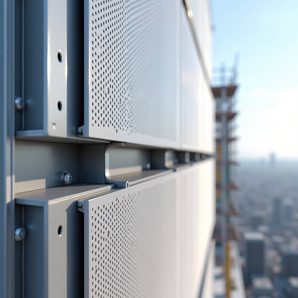
Perforated aluminium angle is often treated as a low-cost framing accessory, but in rainscreen cladding and curtain wall systems it carries real structural responsibility. The perforations that make it light and easy to fix also reduce its section modulus, so the load path, hole pattern, and alloy temper all change how it behaves under wind and dead loads. This article looks at the engineering side of perforated aluminium angle as a support and anchorage component for solid aluminium cladding panels, with worked numbers for fixing spacing, wind suction, and corrosion performance. The goal is to help contractors and facade engineers specify the right profile, hole geometry, and coating for a given project instead of defaulting to whatever stock is on the shelf.
Why the perforations change the structural story
A plain 90° aluminium angle carries load through a continuous leg. Once you add slots or round holes, you remove material from the load path, and the section becomes discontinuous. The practical effect is that a perforated aluminium angle cannot be treated as an equivalent solid angle of the same nominal size. The net section, the stress concentration around each hole, and the effective moment of inertia all drop. For a 40 × 40 × 3 mm angle with staggered 8 mm holes at 25 mm centres, the net area can fall by roughly 15 to 20 percent depending on the pattern. That reduction matters when the angle is used as a fixing bracket for a 2.5 mm solid aluminium panel on a high-rise facade.
Two failure modes dominate. The first is local tear-out at the fixing hole when the angle is loaded in shear. The second is bending of the angle leg under the cantilevered weight of the panel system. Both are governed by the distance from the hole edge to the free edge of the leg, so edge distance is a design parameter, not an aesthetic one. A common rule used in curtain wall detailing is to keep the edge distance at least 1.5 times the hole diameter, and preferably 2 times, before the angle is considered acceptable for load transfer.
Alloy and temper: 6061-T6 versus 6063-T5
Most perforated aluminium angle available on the market is extruded from 6063-T5 or 6061-T6. The difference is not cosmetic. 6061-T6 has a minimum yield strength around 240 MPa in the T6 condition, while 6063-T5 sits closer to 110–130 MPa. For a bracket that carries a panel weight of 30 kg per fixing point, the 6063 profile will need a larger section or a tighter fixing grid to stay within acceptable deflection limits. In practice, structural perforated aluminium angle for facade anchorage is almost always specified in 6061-T6 because the higher strength-to-weight ratio lets the fabricator reduce section size and cost while keeping the same capacity.
There is also a practical difference in how the two alloys respond to drilling and punching. 6063 is softer and easier to punch, which is why many stock perforated angles are made from it. But when the angle is part of a load-bearing bracket, the softer alloy can creep under sustained load, especially at elevated temperatures on a dark facade. The engineer should confirm the temper certificate, not just the alloy designation, before approving the profile for structural use.
Wind suction and fixing spacing on solid panels
Solid aluminium cladding panels fixed to perforated aluminium angle substructures are exposed to both positive and negative wind pressures. On a tall building, suction on the leeward face can exceed 1.5 kPa, and localised pressure at corners and parapets can reach 2.5 to 3.5 kPa. The fixing spacing along the angle must be calculated from the tributary area of each fastener, not guessed from previous jobs. For a 2.5 mm solid panel with a 600 mm fixing grid, each fastener carries roughly 0.36 m² of tributary area. At a design suction of 2.0 kPa, that is about 720 N per fastener in pull-out, which is well within the capacity of a properly sized stainless steel screw, but the angle itself must transfer that force into the support structure without excessive local bending.
The table below gives indicative working loads for a typical 40 × 40 × 3 mm 6061-T6 perforated angle based on standard engineering practice. These are design estimates for planning purposes and should be verified by the project engineer with site-specific wind data.
| Angle size (mm) | Alloy / temper | Hole pattern | Design pull-out (kN) | Design shear (kN) | Max deflection (mm) |
|---|---|---|---|---|---|
| 40 × 40 × 3 | 6063-T5 | 8 mm round @ 25 mm | 1.8 | 2.1 | 1.2 |
| 40 × 40 × 3 | 6061-T6 | 8 mm round @ 25 mm | 3.2 | 3.8 | 0.8 |
| 50 × 50 × 4 | 6061-T6 | 10 mm slot @ 30 mm | 4.6 | 5.4 | 0.6 |
| 60 × 60 × 5 | 6061-T6 | 12 mm slot @ 40 mm | 6.1 | 7.2 | 0.5 |
Hole geometry: round holes versus slots
The choice between round holes and slotted holes changes both assembly and strength. Round pre-drilled holes give a clean, predictable bearing surface and are the safest choice for load-bearing connections. Slotted profiles allow on-site adjustment of the panel position, which is useful when the substructure has accumulated tolerance from the concrete or steel frame. The trade-off is that a slot creates a longer stress concentration and reduces the net section more than a round hole of equivalent width. For a bracket that must transfer real load, the engineer should specify round holes and use a separate slotted adjustment plate if alignment is needed.
Hole orientation also matters. When the long axis of a slot runs parallel to the direction of the applied load, the bearing stress is lower but the tear-out risk along the slot end increases. Running the slot perpendicular to the load gives better tear-out resistance but concentrates the load at a smaller bearing area. The fabricator should mark the load direction on the shop drawing so the installer does not flip the angle and reverse the slot orientation.
Corrosion and coating for external exposure
Perforated aluminium angle used behind a rainscreen is not fully protected from moisture. Condensation, wind-driven rain, and cleaning water all reach the substructure. Bare aluminium forms a self-limiting oxide film, but in coastal or industrial atmospheres, chlorides and sulphates can accelerate localised corrosion, especially at the cut edges of the perforations where the protective oxide is interrupted. For external facade work, the angle should carry a factory-applied coating rather than relying on the natural oxide alone.
Two coating routes are common. The first is anodising, which produces a hard, abrasion-resistant oxide layer 15 to 25 microns thick and is well suited to interior or sheltered applications. The second is a PVDF paint system, typically 25 microns on the exposed face, which gives superior colour retention and resistance to UV and chemical attack. For solid aluminium cladding panels, the industry standard for the panel finish is defined in AAMA 2605 for the highest performance class, and the same coating philosophy should extend to the perforated angle where it will be visible or where it sits in a corrosive environment. The angle supplier should confirm that the coating is applied after the perforations are punched, so the cut edges are protected rather than left bare.
Working with the panel weight and dead load
Solid aluminium cladding panels are heavier than composite alternatives of the same visual thickness. A 2.5 mm solid panel weighs roughly 6.8 kg per square metre, and a 3.0 mm panel about 8.1 kg per square metre. Over a large facade, that dead load accumulates quickly and must be carried by the perforated angle brackets and the fixing screws. The bracket spacing is therefore driven by the panel weight as much as by wind load. For a 3.0 mm panel on a 600 × 600 mm grid, each bracket carries about 0.36 m² of panel, or roughly 2.9 kg of dead weight, plus the wind load. The angle must be sized so that the combined deflection stays below the limit that would cause the panel joint to open or the sealant to fail.
Creep in the fixing screws is another factor. Aluminium has a higher coefficient of thermal expansion than steel, so a bracket fixed to a steel frame with aluminium screws can develop differential movement. Stainless steel fasteners are the norm for this reason, and the perforated angle should be drilled or punched to the exact fastener diameter to avoid oversize holes that allow movement and fretting.
Specification checklist for the procurement team
When a purchasing manager or facade contractor receives a perforated aluminium angle inquiry, the specification should be checked against a short list of engineering parameters rather than a single part number. The alloy and temper must be confirmed with a mill certificate. The hole pattern, diameter, edge distance, and orientation should match the shop drawing. The coating should be specified for the exposure class of the site. And the net section should be verified against the design loads, not assumed to be equal to the solid section.
For projects where the perforated aluminium angle is part of a load-bearing support system for solid aluminium cladding panels, working with a supplier who can provide temper certificates, coating documentation, and cut-to-size service reduces the risk of field modification. Futeng® has supplied perforated aluminium angle and solid aluminium cladding panels to facade contractors across several climate zones, and their technical team can confirm section properties and coating options against a specific loading condition. That level of verification is worth more than a marginal price saving on a component that carries the facade.
Reference standards that guide this work include the aluminium alloy designations in the ISO 209 series, the coating performance classes in AAMA 2605, and the general structural design guidance in the Eurocode for aluminium structures (EN 1999). These documents give the engineer the basis for the net section, deflection limits, and corrosion allowances discussed above.
Closing engineering note
Perforated aluminium angle earns its place in a facade system when it is specified with the same rigour as the panel itself. The perforations are a feature that enables light, adjustable, and fast assembly, but they also change the structural response. Confirm the alloy and temper, check the hole geometry against the load direction, protect the cut edges with a coating matched to the exposure, and size the fixing grid from the actual wind and dead loads. A facade built on a well-specified perforated aluminium angle substructure will hold its geometry and its finish for decades, and that is the outcome every contractor and building owner wants.