Perforated Metal Aluminum Sheet Engineering for Facade Performance and Durability
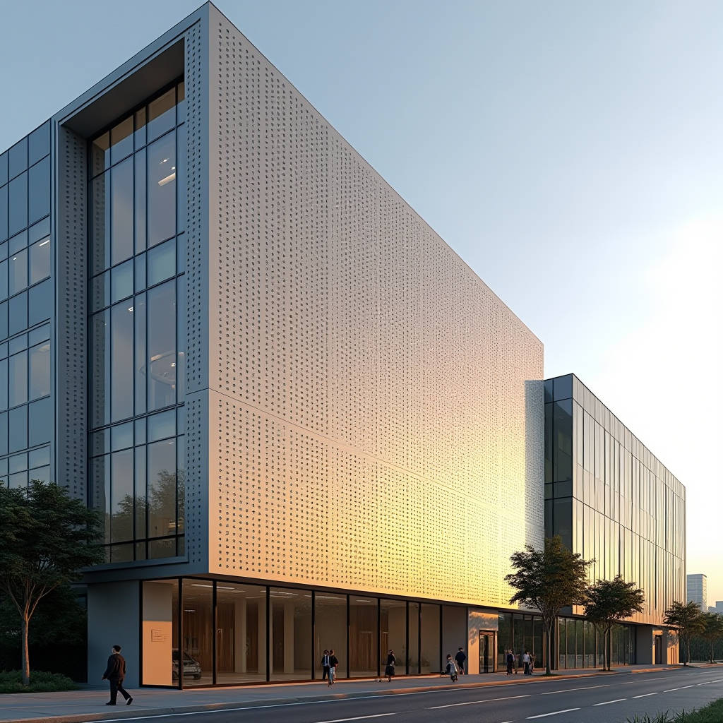
When a facade spec calls for a perforated metal aluminum sheet, the engineering conversation rarely stops at hole diameter and open area. The real decisions sit in the material alloy, the coating system, and the way the panel responds to wind, thermal movement, and acoustic performance. For a solid aluminium cladding panel, those variables are compounded by the fact that the sheet is no longer a monolithic barrier, it is a tuned membrane that must keep its structural integrity while giving up a percentage of its surface to open apertures. This article walks procurement teams and facade contractors through the load calculations, coating selection, and fabrication tolerances that separate a perforated metal aluminum sheet that performs for twenty years from one that fails in the first maintenance cycle. The focus stays on solid 2.0 to 3.0 mm aluminium, not composite alternatives.
Why Open Area Changes Everything
The first number a structural engineer asks for on a perforated metal aluminum sheet is the open area ratio. This single figure drives wind load, acoustic transparency, light diffusion, and the effective stiffness of the panel. Open area is the percentage of the sheet surface removed by the perforation pattern, and it is calculated from hole diameter, spacing, and stagger. For round holes in a 60-degree stagger, the open area formula is approximately 90.7 multiplied by the square of the hole diameter divided by the square of the pitch. A 3 mm hole on a 5 mm pitch yields roughly 32 percent open area, while a 5 mm hole on a 10 mm pitch drops to about 22 percent.
That percentage is not cosmetic. As open area climbs, the remaining material between the holes carries a higher effective stress, and the panel's flexural stiffness falls faster than the open area rises. A panel at 40 percent open area can lose more than half of its bending stiffness compared with a solid sheet of the same thickness. For a solid aluminium cladding panel, this means the perforation pattern must be treated as a structural reduction factor, not a decorative afterthought. The design team should request a perforation reduction factor from the fabricator and apply it to the deflection and stress checks required under the governing wind load code.
Alloy Selection for Perforated Facade Panels
Not every aluminium alloy survives the punching process and the service environment with equal grace. For architectural perforated metal aluminum sheet, the practical field is dominated by three alloys. Alloy 3003 offers excellent formability and corrosion resistance at a moderate cost, which makes it the default for most flat perforated panels and rainscreen applications. Alloy 5052 adds significantly higher strength and better fatigue resistance, which matters on larger panels or in high-wind coastal zones where the perforation pattern creates stress concentrations around every hole. Alloy 6061-T6 brings the highest strength of the three, but its temper makes it harder to punch cleanly and more prone to edge burring, so it is usually reserved for structural components rather than large decorative skins.
The temper matters as much as the alloy. A fully annealed sheet punches cleanly but may not hold flatness after fabrication, while a hard temper holds its geometry but risks micro-cracking at the hole edges under repeated flexural load. For solid aluminium cladding panels in the 2.0 to 3.0 mm range, most experienced fabricators specify 3003-H14 or 5052-H32 as the working balance between punch quality and dimensional stability. The alloy choice should be documented on the shop drawing and matched to the coating system, because some pretreatments and finishes behave differently across alloys.
Coating Systems That Survive the Elements
A perforated metal aluminum sheet exposes far more edge surface than a solid panel. Every punched hole creates a raw aluminium edge that must be protected by the finishing system, otherwise the facade develops a telltale white oxide bloom around each aperture within a couple of seasons. This is the single most common field failure on perforated aluminium facades, and it is entirely preventable with the right coating specification.
For exterior architectural work, the PVDF (polyvinylidene fluoride) system remains the industry benchmark. A proper PVDF finish applies a primer plus a topcoat to a total dry film thickness of roughly 25 to 30 microns, with the coating formulated to meet the performance criteria set out in AAMA 2605. That standard is the most demanding of the AAMA coating specifications, covering colour retention, chalk resistance, and erosion resistance over a 10-year accelerated exposure. For coastal or industrial environments, specifying AAMA 2605 rather than the lighter 2603 or 2604 specification is the difference between a facade that fades in five years and one that holds its colour for two decades.
Anodizing is a legitimate alternative for a perforated metal aluminum sheet, particularly where the architect wants a metallic, non-painted appearance. A 20 to 25 micron architectural anodic coating meets the AA-M12C22A41 designation and offers excellent UV stability because the colour is integral to the oxide layer rather than a surface paint. The trade-off is that anodized surfaces are more sensitive to alkaline cleaners and cement splatter on site, so the installation sequence must protect the panels from mortar and wash-down chemicals. Powder coating is the economical interior or semi-exposed option, but it struggles to deliver the same film thickness uniformity inside small perforation holes, which can leave the hole walls under-protected.
| Coating System | Typical DFT | Relevant Standard | UV / Colour Retention | Best Use |
|---|---|---|---|---|
| PVDF (2-coat) | 25-30 microns | AAMA 2604 | Good, 5-10 yr warranty | Standard exterior facades |
| PVDF (3-coat) | 30-35 microns | AAMA 2605 | Excellent, 20 yr performance | Coastal / high-UV facades |
| Architectural Anodize | 20-25 microns | AAMA 611 / AA-M12C22A41 | Excellent, integral colour | Metallic aesthetic, high-UV |
| Polyester Powder | 60-80 microns | Qualicoat Class 1 | Moderate, 5 yr | Interior / sheltered soffits |
Wind Load and Deflection on Perforated Panels
The structural analysis of a perforated metal aluminum sheet cannot simply reuse the deflection limits of a solid panel. The open area reduces the effective section modulus, and the perforation pattern creates a grid of stress raisers at every hole edge. A practical engineering approach is to apply a perforation reduction factor to the panel's elastic modulus and then run the deflection check against the project's specified limit, typically L/60 to L/90 for a rainscreen panel depending on the cladding standard in force.
For a 3.0 mm solid aluminium panel spanning 1200 mm between supports, a solid sheet under a 1.5 kPa wind load will deflect well within typical limits. The same panel at 35 percent open area can see deflection increase by 40 to 60 percent, which on a long span can push the panel past the acceptable visual limit and cause the perforation pattern to read as a wavy surface in raking light. The fix is rarely to thicken the sheet, which adds cost and weight, but to reduce the support spacing, add intermediate stiffening, or select a tighter hole pattern that preserves stiffness while still delivering the visual open area.
Edge conditions deserve equal attention. A perforated panel that is simply supported on all four edges behaves differently from one with a free edge or a corner cut-out. The fabricator should model the actual support condition, and the shop drawing must show the stiffening returns or hemmed edges that keep the panel flat. Hemming the perimeter of a perforated metal aluminum sheet adds rigidity at minimal cost and is a standard practice on quality facade panels.
Acoustic and Light Performance Considerations
Beyond structure, the perforation pattern is often specified for acoustic absorption or light diffusion, and the two goals pull the design in different directions. For acoustic absorption, the open area needs to be high, typically 25 percent or more, and the panel must be backed by an acoustic cavity and a sound-absorbing media such as mineral wool or a non-combustible acoustic fleece. The perforation acts as a Helmholtz resonator, and the absorption peak is tuned by the hole diameter, the panel thickness, and the depth of the air cavity behind the panel. This is why an acoustic perforated facade is a tuned assembly, not a standalone sheet, and the backing specification is as important as the hole pattern.
For light diffusion, the perforation pattern creates a dappled shadow effect on the interior or on the surface behind the panel. The ratio of hole diameter to sheet thickness affects how sharply the light cuts through, with thinner sheets producing crisper shadows and thicker sheets producing a softer, more diffused effect. On a solid aluminium cladding panel, the specifier should decide early whether the goal is acoustic absorption, light control, or pure visual texture, because the optimal open area and hole geometry differ for each. Trying to satisfy all three with one pattern usually produces a panel that does none of them well.
Fabrication Tolerances and Hole Quality
The quality of a perforated metal aluminum sheet is decided at the punch, not at the coating line. Burrs on the hole edges are the first sign of a poor fabrication, and they are unacceptable on an architectural facade because they snag the coating, create corrosion initiation points, and look rough in close inspection. A reputable fabricator deburrs or vibratory-tumbles the sheet after punching, and the finished hole should be clean and free of raised edges on both faces.
Hole alignment and spacing tolerance also matter over large panels. A pattern that drifts by more than a fraction of a millimetre across a 3-metre panel becomes visually obvious when the panel is viewed in raking light, and it makes adjacent panels impossible to match at the joint. The specification should call out a hole position tolerance and a burr height limit, and the shop drawing should show the pattern origin point so every panel in a run is punched from the same datum. For a project with hundreds of panels, pattern consistency is what makes the facade read as a single, deliberate surface rather than a collection of mismatched sheets.
Specifying for Long-Term Performance
Writing a robust specification for a perforated metal aluminum sheet comes down to a handful of decisions made early. Lock the alloy and temper to the structural and forming requirements. Select the coating system against the project's environmental exposure, and require the coating standard to be met, not just claimed. Define the open area, hole pattern, and support spacing so the structural engineer can check deflection and stress properly. Set fabrication tolerances for burr height and hole alignment, and require a sample panel for approval before production begins.
A reliable supplier such as Futeng® can support this process by providing the perforation reduction factors, coating certifications, and shop drawing review that turn a decorative concept into a buildable, durable facade component. The panels should be delivered with the coating system documented and the tolerances verified, so the contractor can install with confidence and the building owner can expect a facade that keeps its appearance and performance for decades.
The engineering discipline is straightforward: treat the perforation as a structural variable, protect every hole edge with a finish that meets the exposure, and verify the fabrication quality before the panels leave the plant. Do that, and a perforated metal aluminum sheet becomes one of the most durable and visually rewarding cladding choices available to the modern facade.